2505
7 Flange blade inclination
In the case of fixed flanges calculated according to the above calculation procedure, especially in the case of larger diameters, the inclination of the flange sheet γ can become so great that leakage occurs.
It must be taken into account that the various gasket types and materials show great differences in their suitability to allow tight flange joints even with changing flange blade inclinations.
The permissible compressibility or plastic deformability, in conjunction with the geometry, gives a measure of the permissible angle in the installed condition.
In the explanations to this standard, reference values are given for the permissible flange leaf inclination of two flanges in the installed condition, depending on the gasket forms.
For flange blade inclinations greater than 1°, the bending of the bolts must be taken into account.
The flange blade inclination due to the inverted moment in the installed condition according to section 5.1 is calculated as follows:
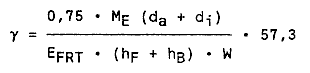
For flanges with a tapered approach, W=WA must also be calculated according to equation (31) for all diameters di > 1050. Furthermore, the following applies:
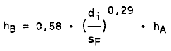
For weld-on flanges where the pipe or shell is connected to the flange sheet without a tapered transition, the following is required

and it applies:
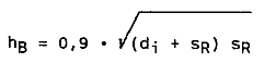
For loose flanges, W applies according to equation (39) and hB = 0
Although AD fact sheet B 8 recommends "...for soft-material gaskets and metal soft-material gaskets to limit the flange sheet inclination in the order of about 0.5 to 1°...", it does not specify how this flange sheet inclination is to be determined.
The draft of DIN 2505 of November 1972 does give a formula for the blade flange slopes, but at the same time states in the footnote that "the equations for calculating the flange blade slope have been established on the basis of numerous tests. Their proving in practice must be observed." In conclusion, it can be said that a blade pitch calculation only makes sense if it is calculated with actual loads and not with required loads as stated in the German regulations. It is certainly not an elegant way to give empirical formulas and then compare them with practice. Incidentally, because of the variety of flange designs that occur in practice, this way is doomed to failure. The blade flange slope can only be determined cleanly for all load cases if the deformation calculation is carried out as presented.
The construction of the so-called "bracing diagram" is also related to the deformation calculation. Both the DIN preliminary standards of October 1964 and the draft DIN 2505 of November 1972 and the supplement deal with the subject and also give relationships for the calculation of the individual spring rates, but they calculate with required and not with actual bolt forces and therefore also incorrectly.
The flange calculation according to ASME Code determines stresses on the most highly stressed point and prescribes limits that must not be exceeded. The stresses are determined taking into account the boundary loads from the deformation of the conical transition and the connected shell with the aid of graphically displayed auxiliary variables. The linear material law is assumed.
The bolt force in the installed condition is calculated as the product of the arithmetic mean of the minimum and effective bolt area and the permissible bolt stress. The bolt force in the operating condition is composed of the internal compressive force and the sealing force required for the respective seal.
The determination of the corresponding internal forces is carried out with the help of the step body method. The change in bolt force during the load change and after the force superposition due to the internal pressure load is not determined. Therefore, again fictitious bolt loads are used, which cannot exist in the real flange connection.
Nevertheless, the calculation method of the flange-to-flange connection according to the ASME code is more logical and reliable than that according to the German regulations. It generally provides larger blade flange heights and is superior above all for large flanges above NW 1000.
It is possible to connect a fatigue consideration, as well as to perform a stress analysis on other flange sections. By the way, the ASME regulation, just like the German regulations, forgets the quite different conditions at a flange-lid joint, where the relatively large lid inclination due to the internal pressure results in a strong decrease of the bolt force and then, of course, also of the sealing force. In addition, there is the gap of the cover in the area of the gasket, which is of decisive importance for the tightness of some gaskets.
Even more complicated deformation ratios are found in a flange connection consisting of a flange and a tube plate, or two flanges and a clamped tube plate. In these cases, a deformation calculation is very extensive and is rarely performed. Experience must then of necessity replace a clear mathematical proof of tightness.
From: "M. Podhorsky, H. Krips Wärmetauscher - Aktuelle Probleme der Konstruktion und Berechnung, FDBR Fachbuchreihe Band 5".