KRVE
|
|
|
|
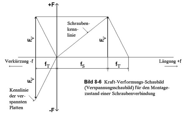
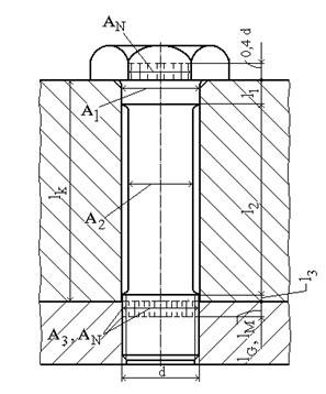
Fig. 8-7 Co-springing individual elements of an expansion bolt |
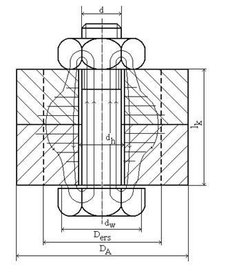
Fig. 8-8 Pressed areas in a through-hole connection (schematic) |
The force play in a flange connection, as it prevails in the various operating conditions, can be illustrated by its stress diagram. The flange connection is seen as a spring system in a flow of forces, consisting of the bolts, the two flanges and the gasket.
|
Figure 3.50 Development of the bracing diagram for pipeline flange connections a) Flange connection without gasket and very stiff flanges. Thus elongation of the bolts alone b) Flanged joint without gasket with elongation of bolts and compression of flanges c) Flange connection without gasket with bolts and flange leaves as stressed parts, compression of flanges neglected d) Flange connection with gasket, in which the bolts as well as the flange sheets act as stressed parts and the gasket acts as a stressed part. Upsetting of the flanges neglected
|
|
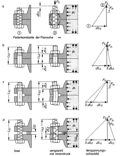
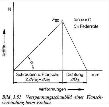
In the stress diagram, in which the spring characteristics of the stressed and tensioned parts of a connection lying in a closed flux of forces are plotted, the elastic changes in shape in the direction of the pipe axis are plotted on the abscissa and the corresponding forces are plotted on the ordinate, with the force deformation ratios of bolts plus flanges usually being shown on one side and that of the gasket on the other (Fig. 3.50). Since the forces change in each case from the installation state through the start-up state to continuous operation, the states mentioned must be recorded in detail by the corresponding stress lines.
The tension diagram represents the interplay of forces between tensioned and tensioned parts.
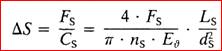
When the n bolts are tightened with the ‑force Fs, each bolt (Fig. 3.51) undergoes elongationDS, the two flanges deflect between bolts ‑and gasket circles by the amount 2- DFl, while the gasket is elastically compressed by D.D
with
Ls = clamping lengths of the screws
ds = for expansion screws the shaft diameter ds
ds = for solid shaft screws, the mean thread diameter

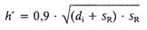
If, for flanges with tapered neck
hA > hF , then h' = hA
If hA < hF, then:

For weld-on collars:
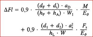
No significant deflection is to be expected in flanges with flat gaskets bearing up to the outer edge or with flange sheets lying flush.
The elastic recovery for flat gaskets is calculated as:
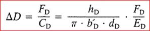
For It gaskets ED »1500 N/mm²
For metal/soft-material gaskets ED »4000 N/mm²
The springback of metallic gaskets can be neglected compared to the springback of bolts and flanges.
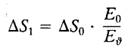
When the flange connection is put into operation, on the one hand, due to the uniformly assumed heating of the entire connection to temperature, there is a relief of the bolt force on:
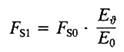
as well as a change of the screw elongation to
On the other hand, the moment of changes due to the internal pressure becoming effective:

in:
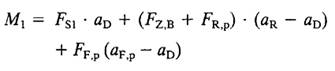
whereby the change of the deflection of a flange in:
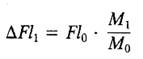
is connected
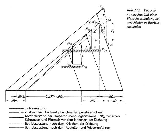
During installation, the screws must be tightened with the screw force FS0 according to the required pre-press force FDV of the gasket.
If the internal pressure p is applied without a change in temperature, the internal pressure force Fp' causes the bolt force to increase to the value FS1, and the sealing force to decrease to FD1. The slope of the spring characteristic curve of bolts and flanges changes in proportion to the external moments.
If, during startup, a temperature difference occurs between the bolts and the fluff corresponding to the elongation difference DWA, additional tensioning of the joint occurs, with the bolt force FS2, and the sealing force increasing to FD2. The slope of the spring characteristic becomes smaller as the elastic modulus changes with temperature.
Usually, the gasket is unable to absorb the increased pressure when exposed to heat. It begins to creep, whereby the joint relaxes until, after a creep distance of DD', the force FD that the gasket can withstand is reached. At the same time as the gasket creeps, however, temperature equalization also takes place between the bolts and flanges at a residual value DWB. The bolt force reaches the value FS3.
During startup, i.e. when the pressure is removed below operating temperature, the pressure on the seal increases, resulting in renewed creep until the bolt force reaches the standing force of the seal FD. If the internal pressure is now applied again, relaxation at the seal follows again on FD4. In order for the joint to remain tight, it must be required that the sealing force FD4 is greater than the operating sealing force FDB required to keep the joint tight during operation. In the case of soft seals, it is often necessary to retighten the joint in order to achieve this condition.
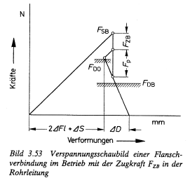
If tensile forces are present in the pipeline, the sealing force decreases and the stress diagram changes as shown in Fig. 3.53.
From: Walter Wagner, Festigkeitsberechnungen im Apparate- und Rohrleitungsbau, 6th ed.