LOBO
Unanchored, round, flat floors and slabs without additional edge moment
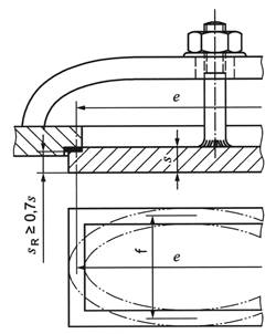
Fig. 1 - Unanchored rectangular or
elliptical slab presented from the inside without additional edge moment
Unanchored, round plates with additional edge moment
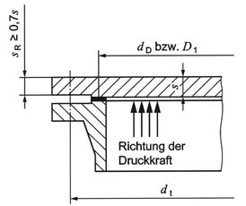
Fig. 3 - Unanchored circular plate with
additional equidirectional edge moment
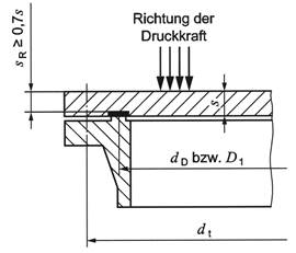
Fig. 4 - Unanchored circular plate with
additional opposing edge moment
Table 1 - Calculation coefficients of unanchored, circular, plane floors and slabs without additional edge moment
|
Design
(schematic view only)
|
Requirements
|
Calculation coefficient C
|
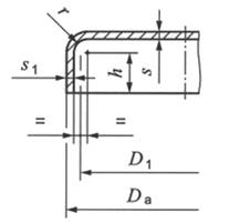
a) carded flat bottom
|
1. brim radius:
|
Since
|
rMinimum dimension
|
|
up to 500
|
30
|
|
> 500 to 1400
|
35
|
|
> 1400 till 1600
|
40
|
|
> 1600 till 1900
|
45
|
|
> 1900
|
50
|
|
And r ≥ 1,3s
|
2. shelf height: h ≥ 3.5s (observe
conditions from section 6.1.1!)
|
0,30
|
|
b) forged or pressed flat bottom
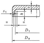
|
1. rim radius

but not less than 8 mm.
2. shelf height h ≥ s
|
0,35
|
|
c) plate welded on both sides
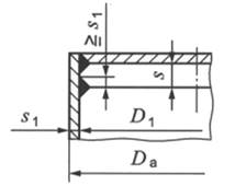
|
Plate wall thickness
|
|
|
s ≤ 3 s1
|
0,35
|
|
s > 3 s1
|
0,40
|
|
d) flat plate on a flanged joint with
continuous gasket
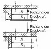
|
D1 ≥ Di
|
0,35
|
|
e) plane plate with relief groove 1)
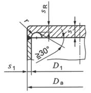
s1= designed wall thickness of the
cylindrical part of the bottom adjacent to the cylindrical shell
|
1. residual wall thickness
in the groove:
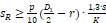 , ,
but not less than 5 mm
and for Da > 1.2 D1 sR
≤ 0.77 s1
2. groove radius:
r ≥ 0.2 s, but not less than 5 mm
and
3. only killed cast steels may be used.
When using plates, the plate must not have any doublings in the area of the
weld seam in a width of at least 3 s12).
4. in the case of special stresses, e.g.
in the creep range, this design is not suitable without special proof.
|
0,40
|
|
f) plate welded on both sides
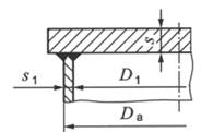
|
Panel wall thickness:
|
|
|
s ≤ 3 s1
|
0,40
|
|
s > 3 s1
|
0,45
|
|
Only killed cast steels may be used. When
using plates, the plate must not have doubles in the area of the weld in a
width of at least 3 s1. 2)
|
|
|
g) flat plate freely supported on both
sides
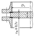
|
Residual wall thickness at gasket circle
or in grooves
sR ≥ 0.7 s
|
0,40
|
|
h) plate welded on one side
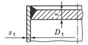
|
Panel wall thickness:
|
|
|
s ≤ 3 s1
|
0,45
|
|
s > 3 s1
|
0,50
|
|
i) partially welded flat plate
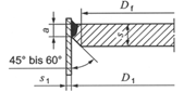
|
Panel wall thickness:
|
|
|
s ≤ 3 s1
|
0,45
|
|
s > 3 s1
Conditions for a:
a ≥ 0.5 s and a ≥ 1.4 s1
Df /D1 ≥ 0.7
|
0,50
|
|
k) flat plate presented from the outside
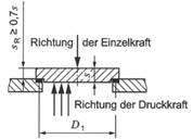
|
1. residual wall thickness at the sealing
circle:
sR ≥ 0.7 s
2. soft material seal
D1 ≤ 500 mm
|
1,25
|
|
l) flat plate presented from the inside
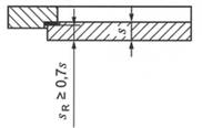
|
Residual wall thickness at the sealing
circle:
sR ≥ 0.7 s
|
0,45
|
|
1) Other
cross-sectional shapes of the relief groove may be more stress-favorable and
are permissible with the appropriate verification.
2) This
is usually fulfilled if the tests have been carried out in accordance with
the steel-iron delivery conditions DIN EN 10160 quality class E 3. This can
already be agreed when the order is placed.
|
AD 2000 B5 Plate 1
Table 2 - Calculation coefficients of circular plane floors and slabs with a central anchorage
|
Embodiment
(schematic representation only)
|
Requirements
|
Calculation coefficient C2
|
carded flat bottom
a) with containment
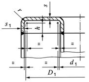
or
b) with through anchor
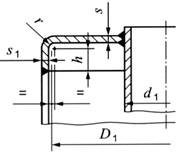
|
1. brim radius:
|
Since
|
rMinimum dimension
|
|
up to 500
|
30
|
|
> 500 to 1400
|
35
|
|
> 1400 till 1600
|
40
|
|
> 1600 till 1900
|
45
|
|
> 1900
|
50
|
|
and r ≥ 1.3s
|
2. shelf height: h ≥ 3.5s (observe
conditions from section 6.5.1!)
|
0,25
|
|
c) plate welded on both sides with through
anchor
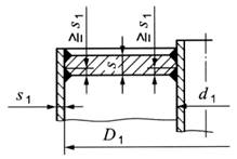
|
Plate wall thickness
|
|
|
s ≤ 3 s1
|
0,30
|
|
s > 3 s1
|
0,35
|
|
d) plate welded on both sides
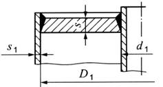
|
Plate wall thickness
|
|
AD 2000 B5 Plate 2
|

|
|
|
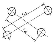
Uniformly distributed anchoring
|
Unevenly distributed anchorage
|
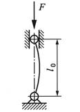
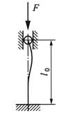
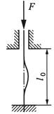
Buckling length for different load cases
|
|
Free rod ends guided in the axis
(tube or anchor between
2 support plates)
|
One rod end clamped, the other guided freely in the axis
(tube or anchor between tube sheet or support plate)
|
Clamped
rod ends guided in the axis
(tube or anchor between2
tube sheets)
|
|
Representation of the load case
|
|
|
|
|
Free buckling length
lK =
|
l0
|
0,7
l0
|
0,5
l0
|
|
Without additional edge torque
|
|
coefficient
|
CA
|
|
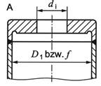
Design
|
 A A
|
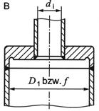
|
|
With additional edge torque
|
|
coefficient
|
CA1
|
|
Design
|
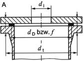
|
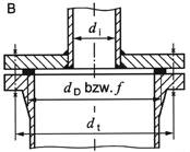
|