Lm-e
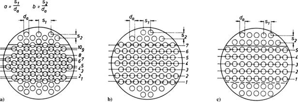
a) staggered tube arrangement, with

a) staggered tube arrangement, with

c) in-line tube arrangement, 
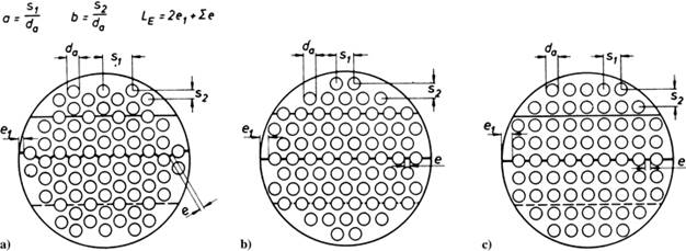
a) staggered tube arrangement, with
 ;
;
b) staggered tube arrangement, with
c) in-line tube arrangement, 
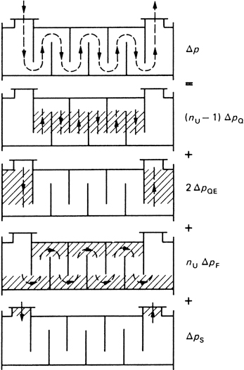
s. Determination of the number of main resistances nW in cross-flow
s. Determination of the number of main resistances nW in cross-flow
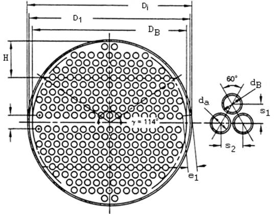
s. Determination of the shortest connection LE
s. Determination of the shortest connection LE
In every second horizontal space between the tube rows, a baffle rod with a round cross-section is inserted horizontally and transversely to the tubes. The diameter dS of each baffle rod is equal to the space between the tube rows.
This means that the tubes and the baffle rods are in contact with each other. A complete set of support grids consists of four support grids built one after the other in a longitudinal direction perpendicular to the centerline of the heat exchanger with a distance SStG between each support grid. In the first support grid the baffle rods of the support grid are arranged horizontally; in the following second support grid they are arranged vertically. In the third and fourth supporting grids, the supporting bars are also arranged horizontally and vertically, respectively; however, they differ from the first and second supporting grids in that the supporting bars are inserted in the spaces between the rows of tubes, which are free of supporting bars in the first and second supporting grids. The four support grids form a unit that can be repeated as required along the tubes in the tube bundle.
|
|
|
|
Type „CM“ |
Type „CS“ |
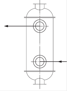
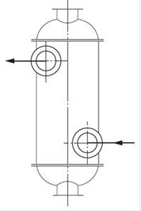
Two heat exchangers with continuous helical baffles
of the same geometry and dimensions and different positions of the nozzles
In every second horizontal space between the tube rows, a baffle rod with a round cross-section is inserted horizontally and transversely to the tubes. The diameter dS of each baffle rod is equal to the space between the tube rows.
This means that the tubes and the baffle rods are in contact with each other. A complete set of support grids consists of four support grids built one after the other in a longitudinal direction perpendicular to the centerline of the heat exchanger with a distance SStG between each support grid. In the first support grid the baffle rods of the support grid are arranged horizontally; in the following second support grid they are arranged vertically. In the third and fourth supporting grids, the supporting bars are also arranged horizontally and vertically, respectively; however, they differ from the first and second supporting grids in that the supporting bars are inserted in the spaces between the rows of tubes, which are free of supporting bars in the first and second supporting grids. The four support grids form a unit that can be repeated as required along the tubes in the tube bundle.