S31
|
Execution D Double ring with bars |
Execution P Foot ring and brackets |
|
|
|
||
|
|
|
|
|
a) details of the welds are not specified in this standard |
c3 ≈ c2 |
Fmax = Tensile force per anchor bolt |
|
2) For the attachment of the lightning protection grounding up to nominal diameter 1 000 mm one hole, above this two diametrically opposite holes. |
||

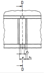
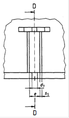
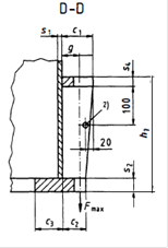
Fig. 2: Foot ring (version S is shown)
|
Version S |
Version Lwith |
|
|
|
|
Shown foot ring with claws |
|
|
Anchor slot or anchor hole set off-axis and arranged symmetrically to the main axis. |
|
|
|
|
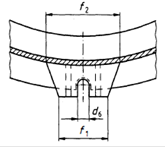
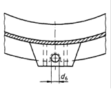
Fig. 3: Design S with anchor slot and design L with anchor hole
If the clear distance between the anchor claws is less than 1.5 times the plate width (f2), a closed ring (double ring) must be used here for design reasons.
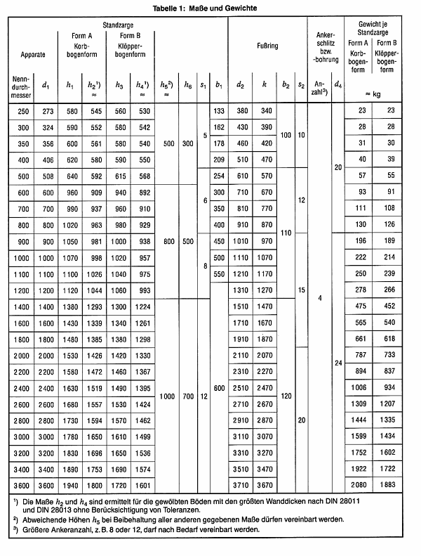
Table 1: Dimensions and anchor bolt forces
The dimension s1 (see Fig. 2) must be determined in the static calculation and must also be checked with the reaction forces from the anchorage.
|
Screws- |
c1 |
c2 |
d6 |
d7 |
e |
f1 |
f2 |
g |
h7 |
s2 |
s4 |
s5 |
Fmax |
|
|
1 0038 |
1 0570 |
|||||||||||||
|
M24 |
80 |
60 |
28 |
32 |
60 |
120 |
180 |
45 |
300 |
35 |
25 |
12 |
35,4 |
53,1 |
|
M30 |
95 |
75 |
35 |
40 |
70 |
130 |
190 |
55 |
56,6 |
84,9 |
||||
|
M36 |
110 |
85 |
42 |
48 |
80 |
160 |
220 |
65 |
16 |
82,8 |
124,2 |
|||
|
M42 |
125 |
100 |
48 |
54 |
90 |
170 |
250 |
75 |
400 |
40 |
30 |
102,1 |
154,4 |
|
|
M48 |
140 |
110 |
56 |
64 |
100 |
180 |
260 |
85 |
134,6 |
203,4 |
||||
|
M56 |
155 |
125 |
66 |
76 |
120 |
220 |
300 |
95 |
45 |
35 |
20 |
186,2 |
281,4 |
|
|
M64 |
175 |
140 |
74 |
84 |
130 |
230 |
330 |
105 |
500 |
50 |
40 |
246,3 |
372,3 |
|
|
M72 x 6 |
195 |
155 |
82 |
92 |
140 |
240 |
340 |
115 |
55 |
45 |
321,2 |
485,6 |
||
|
M80 x 6 |
215 |
165 |
93 |
106 |
160 |
280 |
380 |
125 |
60 |
50 |
25 |
405,0 |
612,2 |
|
|
1) Material no. according to DIN EN 10025 2) The dimensions s2, s4, s5 are reference values for the project planning phase only. In the case of an order, they can be determined by calculation in accordance with AD leaflet S 3/1. The geometric conditions required therein must also be observed. |
||||||||||||||
The values for the maximum tensile force of the anchor bolt Fmax in Table 1 were determined with the yield strengths fy,b,k at 20°C, a safety factor S = 2.2 and the core cross-section according to DIN 13-28
General tolerances according to 28007-1 and DIN 8570-D
|
Form A Basket arch shape |
Form B Dished arch form |
|
|
|
|
|
|
B-B enlarged |
Foot ring with anchor hole |
Foot ring with anchor slot |
|
|
|
|
|
Stand frame opening rotated by 90 |
|
|
|
|
|
|
|
1 frame |
5 Reference line |
|
|
2 Foot ring |
6 Anchor slot |
Set free of axes and arranged symmetrically to the main axis |
|
3 Inspection opening with edge reinforcement |
7 Anchor hole |
|
|
4 Ventilation holes: Up to nominal diameter 1 000 mm at least 2 pieces, diameter 60 mm, from nominal diameter 11 00 mm 4 pieces, diameter 1 00 mm. The ventilation holes must be arranged as high as possible. |
8 Connection for grounding for form A and form B |
|
|
1) dimensions to be specified b3, b4 and s3
|
||
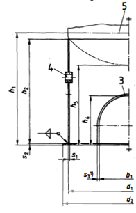
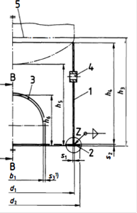
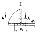
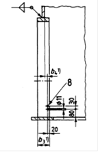
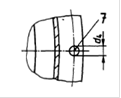
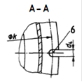
Figure 1: Apparatus with curved bottom