U99N-e
Automatically, UG99 loads all modules, which come into question for calculating the test pressure. Based on the maximum allowable working pressures (MAWP) and the stress ratios (SR) of the individual modules, UG-99 calculates the test pressure,
You can use the program for standard hydrostatic test (UG-99) or pneumatic test (UG-100).
The user can select which modules to consider for calculating the test pressure.
Conditions for being part of the UG 99 module list:
· ASME module
· Calculation for internal pressure
· Module is not hidden
· Module is created by the user and not by the program
For special cases, you can create a User-defined list comprising up to 10 modules. Here you can enter MAWP and SR values manually.
Allows adding modules / components, which are not shown in the automatic UG 99 module list, or components which cannot be calculated (, yet).
Module description:
Description of the component
MAWP
Maximum allowable working pressure (at top of the vessel). Equals the maximum allowable design pressure pD
pD = p0 – Dp
p0: Design pressure
Dp: hydrostatic head
It can be determined by increasing the design pressure until the vessel fulfils only just the strength conditions.
Attention: When increasing the pressure, it must be ensured that values originating from other modules, (e.g. required wall thickness of shell, flange moment) reflect the increase. In the ideal case, these values and the design pressure are connected.
SR
Ratio of allowable stress under test conditions and allowable stress under design conditions.
SR = STest / SDesign

Allows adding modules / components, which are not shown in the automatic UG 99 module list, or components which cannot be calculated (, yet).
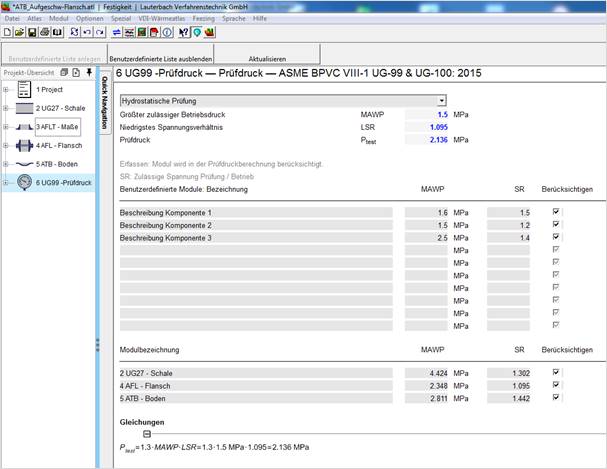
The already created list is hidden and does not take part in the test pressure calculation. It is stored with the ATL file and can be used at any time.
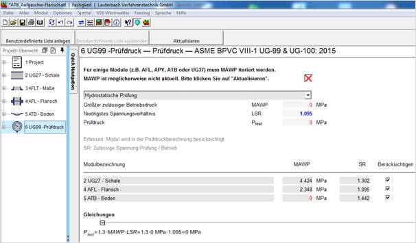
For some modules (e.g. AFL, APY, ATB or UG37) the MAWP must me determined by iteration. This iteration takes some time and thus is not performed automatically. You can start the calculation with the ‘Refresh’ button.
The test pressure formula:
Pt = 1.3 MAWP x (St /Sd)
Pt = Test Pressure
St = Allowable stress at temperature of hydro test
Sd = Allowable stress at design temperature
Note: (St/Sd) will always be equal to or greater than 1!
Hydro Test Procedure – From the Code
1. Complete all pre-hydro work & examination.
2. Assure vessel & support structure is designed for weight of hydro test liquid.
3. Select hydro test fluid - any non-hazardous liquid below its boiling point.
4. Disconnect or "blind off" appurtenances not to be tested.
5. Vent off high points to remove possible air-pockets.
6. Test fluid should be 30 ºF (17 ºC) above the MDMT but not need exceed 120 ºF (48 ºC)
7. Pressure gauges must be acceptable range. About 2 times test pressure. (Acceptable range is 1½ to 4 times Test Pressure)
8. Pressure gauge should be calibrated.
9. Pressure gauge should be connected directly to vessel. If not visible, another should be connected near operator. (Be sure to understand effect of static head on pressure.)
10. Check tightness of test equipment.
11. Perform pressure test at 1.3 times MAWP corrected for temperature.
12. Minimum inspection pressure: Test Pressure divided by 1.3
A vessel is constructed of a P-1 material. The vessel is stamped MAWP – 300 psi at 800 ºF. Material allowable stress “S” is:
100 ºF = 20,000 Psi
800 ºF = 13,500 Psi
Determine the:
a. Hydrostatic Test Pressure
b. Minimum Inspection Test Pressure
1. Calculate Test Pressure
Givens: MAWP = 300 psi,
St = 20,000 psi,
Sd = 13,500 psi
Formula: Pt = 1.3 MAWP x (St/Sd)
Pt = 1.3 (300) x (20,000/13,500)
Pt = 390 x 1.481
Pt = 577.7 psi
Hydrotest pressure is 577.7 psi at the top of the vessel.
2. Calculate minimum Inspection Test Pressure
Formula: PInsp = Pt /1.3
PInsp = 577.7 /1.3
PInsp = 444.4 psi
Maximum allowable working pressure (at top of the vessel). Equals the maximum allowable design pressure pD
pD = p0 – Dp
p0: Design pressure
Dp: hydrostatic head
It can be determined by increasing the design pressure until the vessel fulfils only just the strength conditions.
Minimum of the allowable working pressures of all individually considered modules / components).
Minimum of the stress ratios of all considered materials. The stress ratio of a material is the ratio of allowable stress under test conditions and allowable stress under design conditions.
SR = STest / SDesign
Bolting materials are only considered for the calculation if:
· 1.3 · SR · SBolt,Design > 0.9 · Re,Bolt (hydrostatic test)
· 1.1 · SR · SBolt,Design > 0.9 · Re,Bolt (pneumatic test)
Comments on test pressure according ASME. The test pressure is determined according to MAWP. See UG99 in ASME regulations version 2019.
You can define the MAWP yourself. For example, set the MAWP to design pressure. (MAWP must be at least equal to design pressure)
This results in a correspondingly low test pressure.
The MAWP entered on the nameplate of the boiler applies to the test pressure.
If the test pressure appears too high to you because the MAWP of the construction is high, it is possible to reduce the MAWP itself to minimum design pressure as described above.