UBC-e
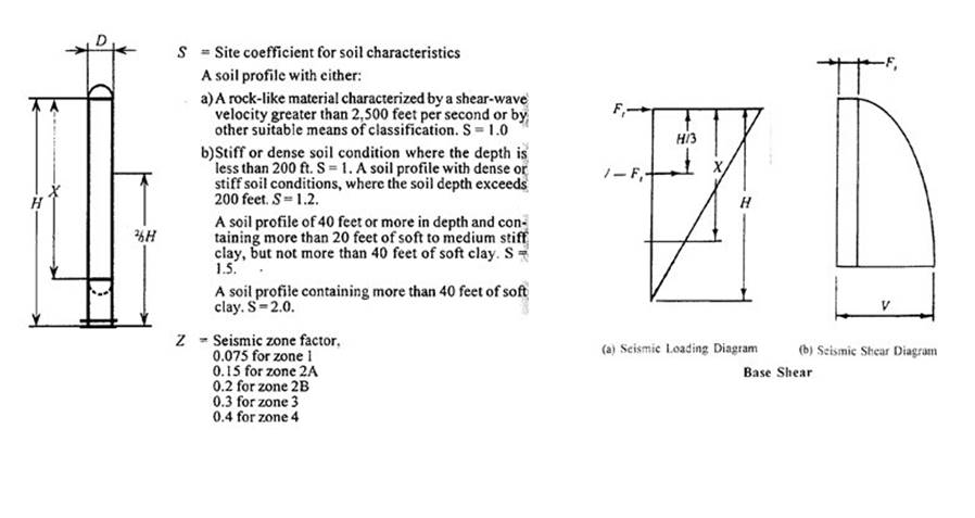
TABLE 16-H—PRESSURE COEFFICIENTS (Cq)
|
STRUCTURE OR PART THEREOF |
DESCRIPTION |
Cq FACTOR |
|
1. Primary frames and Systems |
Method 1 (Normal force method) Walls: Windward wall Leeward wall Roofs1: Wind perpendicular to ridge Leeward roof or flat roof Windward roof less than 2:12 (16.7%) Slope 2:12 (16.7%) to less than 9:12 (75%) Slope 9:12 (75%) to 12:12 (100%) Slope > 12: 12 (100%) Wind parallel to ridge and flat roofs |
0.8 inward 0.5 outward
0.7 outward
0.7 outward 0.9 outward or 0.3 inward 0.4 inward 0.7 inward 0.7 outward |
|
|
Method 2 (Projected area method) On vertical projected area Structures 40 feet (12 192 mm) or less in height Structures over 40 feet ( 12 192 mm) in height On horizontal projected area1 |
1.3 horizontal any direction 1.4 horizontal any direction 0.7 upward |
|
2. Elements and components not in areas of discontinuity2 |
Wall elements All structures Enclosed and unenclosed structures Partially enclosed structures Parapets walls |
1.2 inward 1.2 outward 1.6 outward 1.3 inward or outward |
|
|
Roof elements3 Enclosed and unenclosed structures Slope < 7:12 (58.3%) Slope 7:12 (58.3%) to 12:12 (100%) Partially enclosed structures Slope < 2:12 (16.7%) Slope 2:12 (16.7%) to 7:12 (58.3%) Slope > 7:12 (58.3%) to 12:12 (100%) |
1.3 outward 1.3 outward or inward
1.7 outward 1.6 outward or 0.8 inward 1.7 outward or inward |
|
3. Elements and components in areas of discontinuities2'4'5 |
Wall corners6 Roof eaves, rakes or ridges without overhangs6 Slope < 2:12 (16.7%) Slope 2:12 (16.7%) to 7:12 (58.3%) Slope > 7:12 (58.3%) to 12:12 (100%) For slopes less than 2:12 (16.7%) Overhangs at roof eaves, rakes or ridges, and canopies |
1.5 outward or 1.2 in ward
2.3 upward 2.6 outward 1.6 outward
0.5 added to values above |
|
4. Chimneys, tanks and solid towers |
Square or rectangular Hexagonal or octagonal Round or elliptical |
1.4 any direction 1.1 any direction 0.8 any direction |
|
5. Open-frame towers7'8 |
Square and rectangular Diagonal Normal Triangular |
4.0 3.6 3.2 |
|
6. Tower accessories (such as ladders, conduit, lights and elevators) |
Cylindrical members 2 inches (51 mm) or less in diameter Over 2 inches (51 mm) in diameter Flat or angular members |
1.0 0.8 1.3 |
|
7. Signs, flagpoles, lightpoles, minor structures8 |
|
1.4 any direction |
1) For one story or the top story of multistory partially enclosed structures, an additional value of 0.5 shall be added to the outward Cq. The most critical combination shall be used for design. For definition of partially enclosed structures, see Section 1616.
2) Cq values listed are for 10-square-foot (0.93 m2) tributary areas. For tributary areas of 100 square feet (9.29 m2), the value of 0.3 may be subtracted from Cq, except for areas at discontinuities with slopes less than 7 units vertical in 12 units horizontal (58.3% slope) where the value of 0.8 may be subtracted from Cq. Interpolation may be used for tributary areas between 10 and 100 square feet (0.93 m2 and 9.29 m2). For tributary areas greater than 1,000 square feet (92.9 m² use primary frame values.
3) For slopes greater than 12 units vertical in 12 units horizontal (100% slope), use wall element values.
4) Local pressures shall apply over a distance from the discontinuity of 10 feet (3048 mm) or 0.1 times the least width of the structure, whichever is smaller.
5) Discontinuities at wall comers or roof ridges are defined as discontinuous breaks in the surface where the included interior angle measures 170 degrees or less.
6) Load is to be applied on either side of discontinuity but not simultaneously on both sides.
7) Wind pressures shall be applied to the total normal projected area of all elements on one face. The forces shall be assumed to act parallel to the wind direction.
8) Factors for cylindrical elements are two thirds of those for flat or angular elements.
|
OCCUPANCY CATEGORY |
OCCUPANCY OR FUNCTIONS OF STRUCTURE
|
IMPORTANCE FACTOR |
||
|
SE1SMIC I |
SEISMIC Ip |
WIND Iw |
||
|
l. Essential facilities2
|
Group I, Division 1 Occupancies having surgery and emergency treatment areas Fire and police stations Garages and shelters for emergency vehicles and emergency aircraft Structures and shelters in emergency-preparedness Centers Aviation control towers Structures and equipment in government communication centers and other facilities required for emergency response Standby power-generating equipment for Category 1 facilities Tanks or other structures containing housing or supporting water or other fire-suppression material or equipment required for the protection of Category 1, 2 or 3 structures |
1.25
|
1.50
|
1.15
|
|
2. Hazardous facilities
|
Group H, Divisions 1, 2, 6 and 7 Occupancies and structures therein housing or supporting toxic or explosive chemicals or substances Nonbuilding structures housing, supporting or containing quantities of toxic or explosive substances that, if contained within a building, would cause that building to be classified äs a Group H, Division 1, 2 or 7 Occupancy
|
1.25
|
1.50
|
1.15
|
|
3. Special occupancy structures-1
|
Group A, Divisions 1, 2 and 2.1 Occupancies Buildings housing Group E, Divisions 1 and 3 Occupancies with a capacity greater than 300 students Buildings housing Group B Occupancies used for College or adult education with a capacity greater than 500 students Group I, Divisions 1 and 2 Occupancies with 50 or more resident incapacitated patients, but not included in Category 1 Group I, Division 3 Occupancies All structures with an occupancy greater than 5,000 persons Structures and equipment in power-generating stations, and other public utility facilities not included in Category 1 or Category 2 above, and required for continued Operation
|
1.00
|
1.00
|
1.00
|
|
4. Standard occupancy structures-1
|
All structures housing Occupancies or having functions not listed in Category I, 2 or 3 and Group U Occupancy towers
|
1.00
|
1.00
|
1.00
|
|
5. Miscellaneous structures
|
Group U Occupancies except for towers
|
1.00
|
1.00
|
1.00
|
1) The limitation of Ip for panel connections in Section 1633.2.4 shall be 1.0 for the entire connector.
2) Structural observation requirements are given in Section 1702.
3) For anchorage of machinery and equipment required for life-safety Systems, the value of Ip shall be taken as 1.5.
MINIMUM BASIC WIND SPEEDS
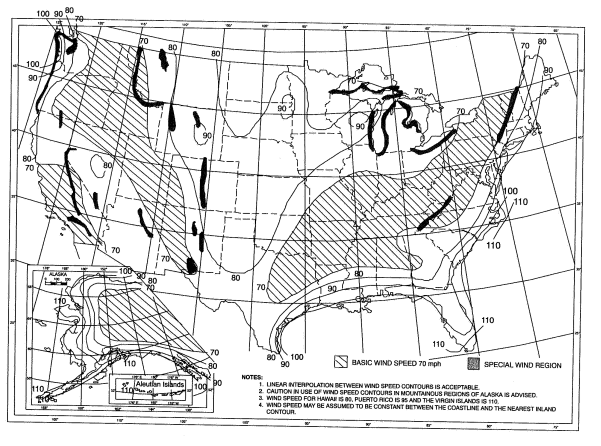
FIGURE 16-1—MINIMUM BASIC WIND SPEEDS IN MILES PER HOUR (x 1.61 for km/h)
SEISMIC ZONE MAP OF THE UNITED STATES
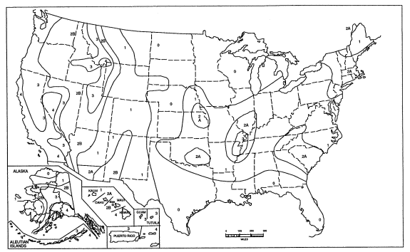
FIGURE 16-2—SEISMIC ZONE MAP OF THE UNITED STATES For areas outside of the United States, see Appendix Chapter 16.