Task / Example
1. Which minimum thickness is required for the flange?
2. Which torque is required for the bolts?
The calculation module 1591 creates a complete documented calculation of a flange joint. All necessary values are documented in the output. The required input values are summarized in the following.
|
Device drawing |
-> |
Flange geometry |
|
Device drawing |
-> |
Operation data, pressure, temperature |
|
Part list |
-> |
Bolt geometry, gasket geometry |
|
Standards or the corresponding modules |
-> |
Gasket parameters, exact bolt geometry |
|
|
Start the stress calculation program from the start menu (Start -> Programs) or using the LV-symbol.
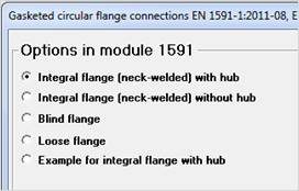
Select calculation module 1591 in the module overview. A selection mask with the title: Options in module 1591 appears |
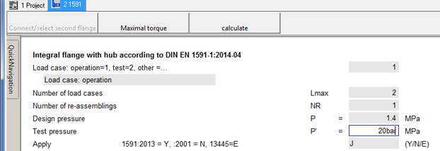
In the upper part of the input mask, you select the operation load case, in order to calculate the flange joint for operation conditions. Enter also the test pressure P’ = 20 bar. The program converts the unit automatically to MPa
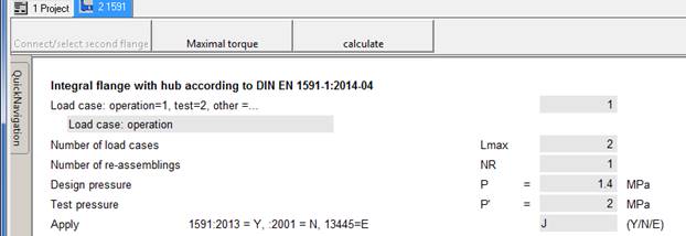
Please note:
For each load case according to EN 1591, as for instance operation and test pressure, the installation load case is also calculated and documented in the mask. Since the required gasket force according to EN 1591 requires the maximum of all load cases, the value for test conditions must also be calculated. The recalculation of the maximum gasket force can be performed at the end of the calculation mask (see below).
Frequently the usage factor of the flange joint for the installation case, i.e. after tightening the bolts under room temperature without pressure loading, is greater than for operation conditions. After application of internal pressure, the gasket surface pressure decreases because a part of the bolt preloading is released.
The materials are managed in the material data base and the material properties are transferred to the stress calculation program by the material server program. Several options are available for the selection of material:
· Input of the material name
· Search of materials by input of a part of the name
· Selection among a list of all materials
· Step wise reduction of the full material list by specification, regulation and product form
Usually, for the bolt temperature, you can specify the flange temperature (here 200°C). Different temperatures or different coefficients of thermal dilatation of flange and bolts can produce large thermal deformations and thus large stresses.
To design the flange material saving, the materials should have similar coefficients of thermal expansion. After specification of the bolt temperature, you enter the first letters of the material name in the input field for the bolt material, e.g. A4:
The selection screen of the material sever appears and you select the desired material, e.g. bolt A4-70 acc. AD-W2:
For the flange material you enter the name 1.4580 (EN10028-7 AD W-2) in the field for the flange material and also for the shell material:
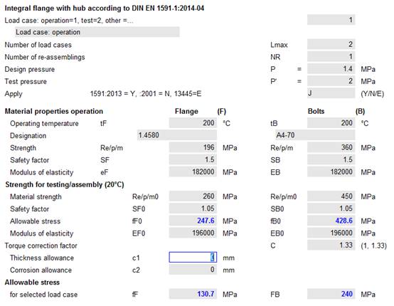
The thickness allowance c1 is not in the material data base and must be entered manually!
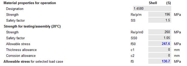
As the material is the same for the shell and the flange, you may select the material in the material list by double click.

Here the allowance must be entered as well.
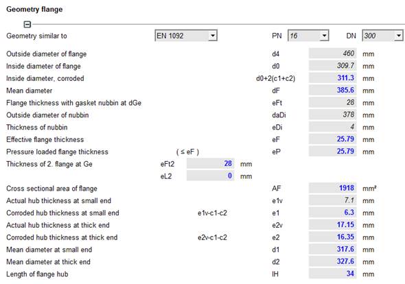
The pipeline flange may be specified in the drawing as steel flange acc. EN 1092-1, and must conform with the design device flange in the connecting dimensions as: bolt circle diameter, inside diameter, gasket geometry, bolt hole diameter etc.
Therefore, specify: flange acc. DIN EN 1092-1 in the selection mask.

After selection of the flange type (here weld neck flange), the flange geometry is determined by entering the nominal diameter and the pressure level.
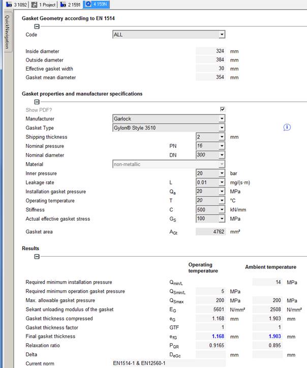
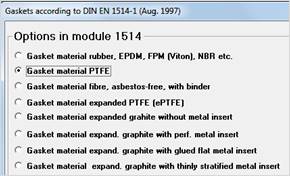
Select the type of gasket in the selection mask of module 1514. A PTFE gasket according to EN 1514 may be specified in the part list
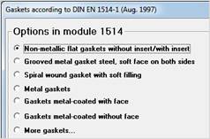
Select: Flat gasket acc. to EN 1514-1 in the selection mask.
The program can now transfer inside diameter and outside diameter of the gasket and other characteristic gasket data like gasket seating from the module 1514.

|
|
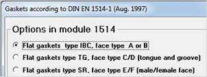
The exact type is specified:
Flat gaskets type IBC, face type A or B
|
|
|
|
Non-metallic flat gaskets without / with insert
|
|
|
|
Gasket material PTFE
|
|
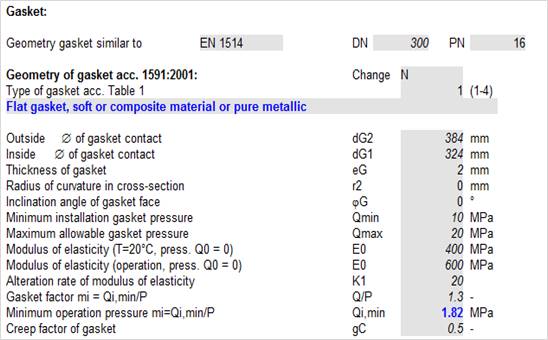
By specification of the flange diameter, pressure level, as well as type and temperature of the gasket, most of the values can automatically be transferred to the mask for the flange calculation, as e.g.:
· Flange inside diameter, flange outside diameter
· Bolt circle diameter, number of bolts, bolt hole diameter
· Gasket inside and outside diameter
· Minimum and maximum surface pressure of the gasket etc.
Pressure and temperature have also been specified.
Finally, additional specifications are necessary:
· In the first instance the operation load case should be calculated, because it determines usually the dimensions.
· The test pressure is also necessary, because the gasket face pressure acc. 1591 must be calculated for all subsequent load cases. The maximum required gasket force is determined at the end of the calculation.
· The materials for flange, device shell and bolts have to be specified.
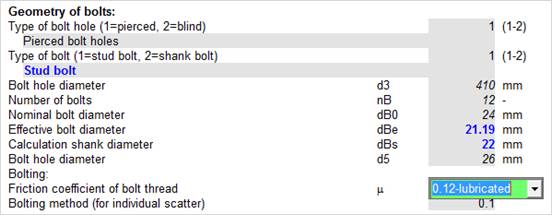
· Additional specifications are the pipe wall thickness, eS the mean pipe diameter dS and the friction coefficient of bolt thread m.
With these specifications, the calculation is finished and the load usage factor of the flange joint is determined. The flange blade thickness can be reduced, as long as the usage factor is below 100%. After modification of the flange geometry or operation data, it is necessary to recalculate the maximum gasket force for operation and test at the end of the mask.
Complete the missing data, as required:
Friction factor of bolt thread m = 0.12
Afterwards, you scroll to the end of the calculation mask to the results.
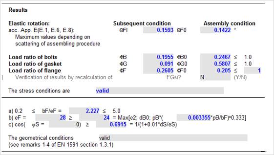
Since the gasket force FGDi must be determined for all subsequent load cases as operation, test, etc., you
have to start a Control Iteration.

In the section ‘For Documentation’ you can see the calculated gasket force.
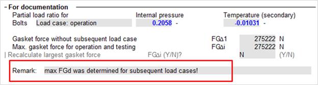
Make sure that in the last remark field this text appears.
|
max FGd was determined for subsequent load cases! |
Now you can extract the requested results from the mask, e.g.:
· Flange efficiency
· Bolt torque for assembling
The operation case can directly be copied by clicking on the tab of module 1591 with the right mouse key and selecting the option Copy Module in the context menu.
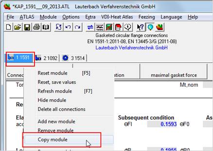
|
Select the option <Copy values and selected options> to retain the type and delete the connections:
|
|
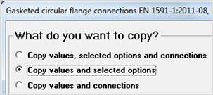
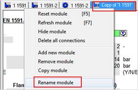
In the new chapter we modify the tab caption with the context menu < Rename module>
|
|
Simply add TEST
|
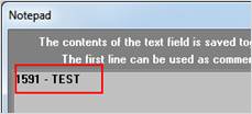
Finally, we specify the load case test:
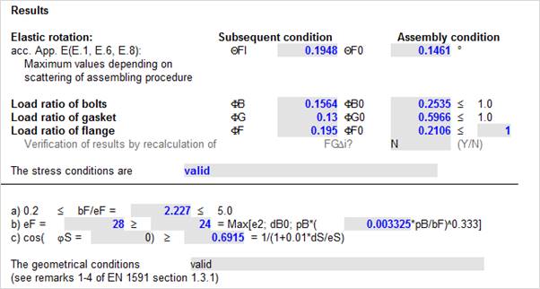
The load ratios for the subsequent load case testing are less than for operation. The values for installation agree for operation and testing. The maximum gasket force has already been calculated and must not be recalculated again.
-> Do not perform a Control Iteration.
Save the calculation using the file menu <File \ Save>.
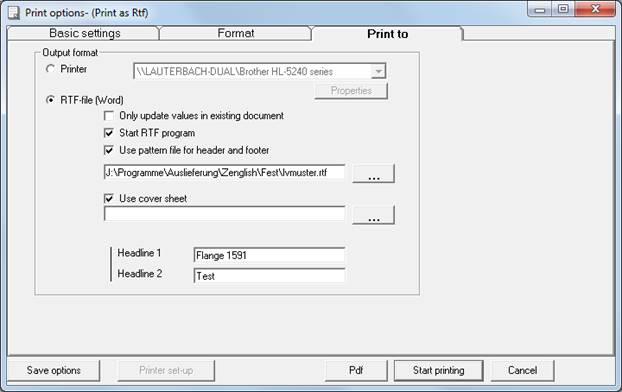
Print the calculation using < File \ Print >. Several options are available (not in the demo version) for the layout of the documentation. Using the option RTF-file (Word) the document can be edited with Word, Notepad or other text programs, saved as file and printed.