ANSI Module
The following nomenclature is used in the equations for pressure design of straight pipe:
c = sum of the mechanical allowances (thread or groove depth) plus corrosion and erosion allowances. For threaded components, the nominal thread depth (dimension h of ASME B1.20.1, or equivalent) shall apply. For machined surfaces or grooves where the tolerance is not specified, the tolerance shall be assumed to be 0.5 min (0.02 in.) in addition to the specified depth of the cut.
D = outside diameter of pipe as listed in tables of standards or specifications or as measured
d = inside diameter of pipe. For pressure design calculation, the inside diameter of the pipe is the maximum value allowable under the purchase specification.
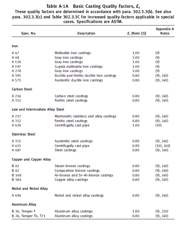
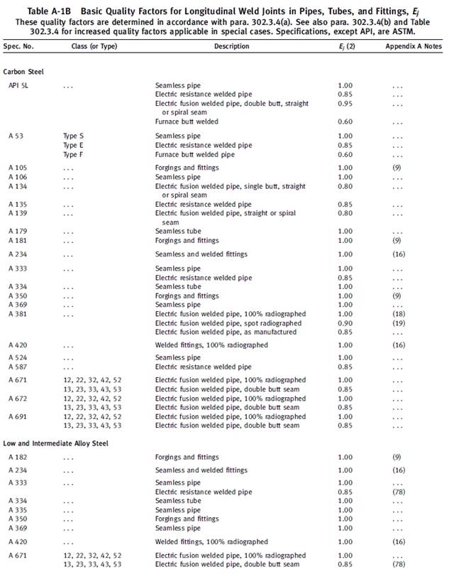
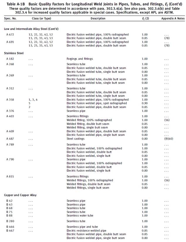
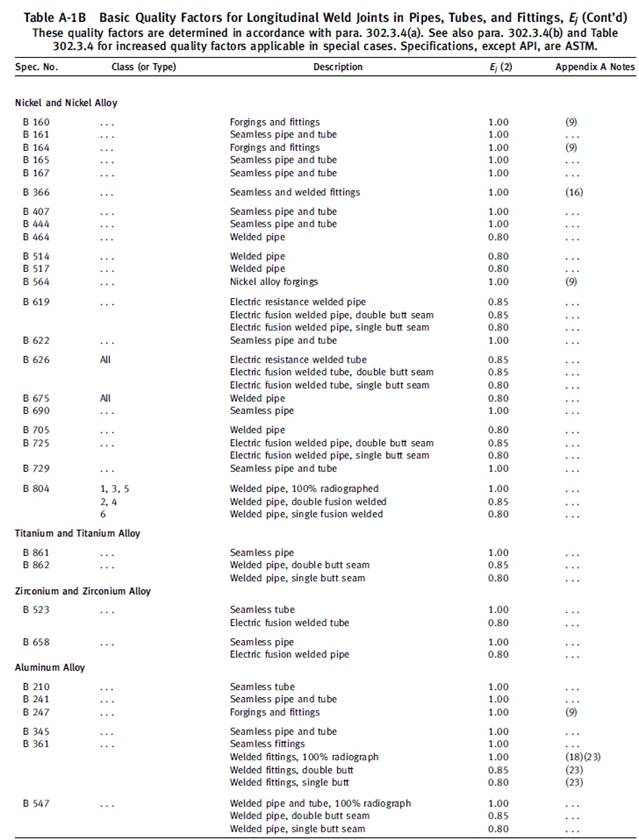
E = quality factor from Table A-1A or A-1B
T = pipe wall thickness (measured or minimum in accordance with the purchase specification)
t = pressure design thickness, as calculated in accordance with para. 304.1.2 for internal pressure or as determined in accordance with para.304.1.3 for external pressure
tm = minimum required thickness, including mechanical, corrosion, and erosion allowances
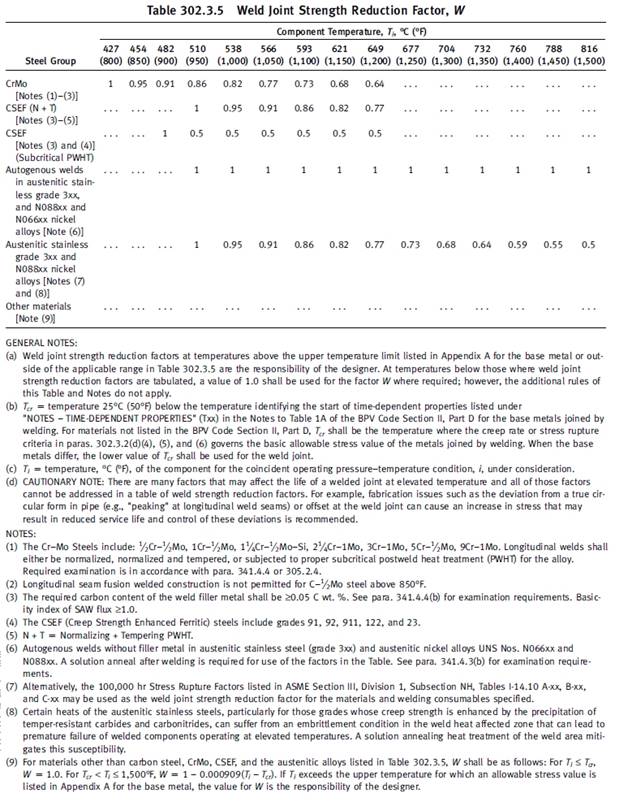
W = weld joint strength reduction factor in accordance with para. 302.3.5(e)
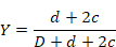
Y = coefficient from Table 304.1.1, valid for t < D/6 and for materials shown. The value of Y may be interpolated for intermediate temperatures.
For t ≥ D/6,
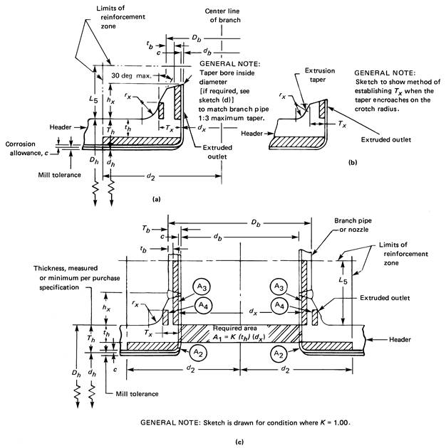
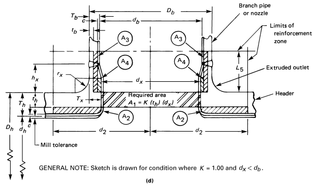
This Figure illustrates the nomenclature of para. 304.3.4. It does not indicate complete details or a preferred method of construction.
Requirements in para. 345.2 apply to more than one type of leak test.
345.2.1 Limitations on Pressure
(a) Stress Exceeding Yield Strength. If the test pressure would produce a nominal pressure stress or longitudinal stress in excess of yield strength at test temperature, the test pressure may be reduced to the maximum pressure that will not exceed the yield strength at test temperature. [See paras. 302.3.2(e) and (f).]
(b) Test Fluid Expansion. If a pressure test is to be maintained for a period of time and the test fluid in the system is subject to thermal expansion, precautions shall be taken to avoid excessive pressure.
(c) Preliminary Pneumatic Test. A preliminary test using air at no more than 170 kPa (25 psi) gage pressure may be made prior to hydrostatic testing to locate major leaks.
Weld Joint Strength Reduction Factor, W. At elevated temperatures, the long-term strength of weld joints may be lower than the long-term strength of the base material. For longitudinal or spiral welded piping components, the product of the allowable stress and the applicable weld quality factor, SE, shall be multiplied by the weld joint strength reduction factor, W, when determining the required wall thickness for internal pressure in accordance with para. 304. The designer is responsible for the application of weld joint strength reduction factors to welds other than longitudinal and spiral (e.g., circumferential). The weld joint strength reduction factor, W, is equal to 1.0 when evaluating occasional loads such as wind and earthquake, or when evaluating permissible variations in accordance with para. 302.2.4. The pressure rating or allowable stress for the occasional load or variation condition is not required to be reduced by the weld joint strength reduction factor. It is also not required when calculating the allowable stress range for displacement stresses, SA, in para. 302.3.5(d). The weld joint strength reduction factor only applies at weld locations. The well joint strength reduction factor is the ratio of the nominal stress to cause failure of the well joint to that of the base material for the same duration. Except as provided in (f) below, the well joint strength reduction factor, W, shall be in accordance with Table 302.3.5.