B0-e
A proof of nozzle loads is not necessary if the following conditions are satisfied as well:
· The nozzle pipe must be fully connected to the basic shell.
· The minimum wall thickness of the nozzle pipe must be according to DIN 28115 with ferritic materials, and according to DIN 28 025 part 1 or part 2 with austenitic materials.
· Support lengths and flexibility of the connected pipe must satisfy support length table or flexibility nomogram of AD 2000-Merkblaetter section HP 100 R (LV Module HPR).
·
The diameter of the nozzle di must not be
greater than 0.3*Di.
The design for internal pressure per AD 2000-Merkblaetter B 3, B 9 and B 1
must be done with a 10 percent increased internal pressure, with a
reinforcement of the basic shell and/or the nozzle, if necessary.
· Design is not done for failure due to creep fatigue.
· The number of start-ups and removals does not exceed the allowable numbers per 2000-Merkblatt S1 section 4.2.
Requirements of the Pressure Equipment Directive
Requirements of the PED
In Annex I, Section 3.2, the PED requires that a strength test in the form of a hydrostatic pressure test be carried out as part of the final inspection. This pressure test is intended to check the aspect of the required compressive strength.
The test pressure must be at least equal
to the value specified in section 7.4 of Annex I:
(1) PT = PS * 1,43 or
(2) PT = PS * 1,25 * K20 / KTS
The higher of the two calculated test pressures PT is decisive.
The test pressure factor FP = 1.25 * K20 / KTS in formula (2) above takes into account the temperature-dependent strength values.
The test pressure factor FP = 1.43 in
formula (1) means that in the test state a stress level of 95% of the yield
strength corresponding to a residual safety factor of 1.05 is achieved.
The aforementioned regulations apply to pressure vessels, pressure-retaining equipment, pipelines and assemblies.
Replacement tests for the hydrostatic pressure test
The PED expressly permits substitute tests if the hydrostatic test is disadvantageous or not feasible:
(a) a gas pressure test
(b) other test pressures
(c) verification on a statistical basis
2.1. Gas pressure test
The gas pressure test should only be used in exceptional cases, e.g. if the hydrostatic pressure test is disadvantageous or not possible. If a lower test pressure is used for safety reasons, additional measures must be taken, e.g. non-destructive testing, to achieve an equivalent level of safety.EN13445:
The pressure test is part of the acceptance test.
The hydrostatic test (hydraulic pressure test) is performed as a pressure test as standard.
If this is not appropriate, this test can be replaced as follows:
(a) Pneumatic test (gas pressure test). The gas pressure test is much more dangerous than the hydrostatic test. Therefore, this test may only be carried out under the following conditions:
- Filling the pressure vessels with liquid is inappropriate due to the design and construction;
- the pressure vessels are to be used in processes in which even small traces of liquid cannot be tolerated;
- after timely consultation during the design phase;
2.2 Other test pressures
The level of the test pressure must be chosen so that the hydrostatic pressure test, with due regard to safety factors, ensures that no damage to the pressure equipment occurs.
3. Requirements of the regulations
For the performance of the hydrostatic pressure test, additional aspects have to be considered which are not explicitly stated in the PED but which can be derived from the specifications. The following table considers the essential aspects in the individual regulations:
|
EN 13445-5:2009 |
AD 2000 - HP 30 |
|
|
Calculation of the test pressure or test pressure factor FP |
Information on the calculation of the test pressure factor in EN 13445-5 section 10.2.3.3 Special calculation requirements for vessels of Test Group 4 |
Information on calculation of the test pressure factor in AD 2000 HP 30 Section 4.17 |
|
Testing several pressure spaces |
Details are given in EN 13445-5 section 10.2.3.3.3 |
The pressure test shall be performed separately for each pressure space. Exception: If the partition is designed for differential pressure only (see AD 200 HP 30 No. 4.3) |
|
Time of testing |
Details are given in EN 13445-5 section 10.2.3.2.2 |
- After the last heat treatment - for enamelled containers before enamelling - after plating - after machining - before the application of coatings, insulation, rubber linings, linings, linings, coatings Further information in AD 2000 HP 30 Section 3 |
|
Consideration of the static liquid column during operation and during the pressure test |
Specifications for the consideration of static pressure in EN 13445-5 section 10.2.3.3.1 |
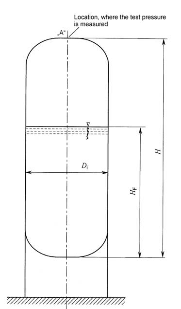
The static pressure only needs to be taken into account if the tension of the vessel wall is increased by more than 5%. Has to be considered if necessary. Details of the feed-through on horizontal and vertical tanks are given in AD 2000 HP 30 section 4.10 |
|
Pressure test for single-layer welded seams |
EN 13445-5 Section 10.2.3.3.1 (c) |
- |
|
Pressure test for vessels operating in the creep range |
EN 13445-5 Section 10.2.3.3.1 (d) |
- |
|
Test pressures over 100 bar |
no special details |
Special protective measures must be taken into account see AD 2000 HP 30 section 4.16 |
|
Test as gas pressure test |
Details are given in EN 13445-5 sections 10.2.3.1 and 10.2.3.4 |
Details of test pressure, local conditions, details of additional NDE tests are given in AD 2000 HP 30 para. 4.16 and 4.19 |
|
Testing on a statistical basis |
EN 13445-5 Annex A.11 |
- |
|
Testing of enamelled or coated vessels |
Details are given in EN 13445-5 section 10.2.3.2.2 |
For details see AD 2000 HP 30 para. 4.18 |
|
Water quality |
Details are given in EN 13445-5 section 10.2.3.2.5 |
no details |
|
Information on the pressure gauge used |
EN 13445-5 Table 9.2.2.1 and section 10.2.3.11 |
- |