Calculation of conical mantles
Fact sheet B2 recalculates an existing geometry! The executed wall thicknesses should be specified as a starting value.
Tapered components are required by the process and are designed symmetrically or asymmetrically (mainly for horizontal apparatus).
Conical shells connected to a cylindrical shell on the same axis (concentric conical shells) by corner joint or by a brim (even if their wall thickness changes) can be calculated according to AD fact sheet B 2.
The formulas given there apply to 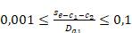 that is, relatively
thin-walled shells. A distinction is made between diverging and converging cone
shells, each of which can be designed with a corner joint or brim.
that is, relatively
thin-walled shells. A distinction is made between diverging and converging cone
shells, each of which can be designed with a corner joint or brim.
The design often depends on the manufacturing possibilities of the equipment manufacturer. Conical heads with brims or brim parts are usually purchased as so-called flanging parts from the head manufacturers and completed accordingly by the equipment manufacturer.
Design forms with dimensioning symbols are e.g. Fig. 1a and 1b
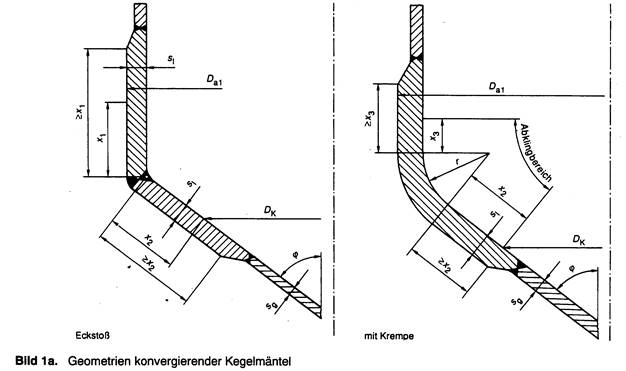
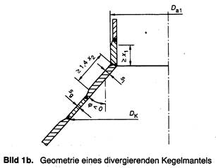
Eccentric taper shells cannot be calculated with AD fact sheet B 2; one possibility is offered by TGL 32 903/06 or the strength catalog (with special designs), but this requires appropriate familiarization with the calculation methodology.

The calculation for asymmetric conical shells applies only if they are connected to cylindrical shells. The sizes α1, D and D1 are to be used as shown in the figure.
For the calculation, a so-called decay region is defined in which the bending stresses arising from geometric changes of the shells at the joints are relieved by appropriate dimensioning.
The decay range (x1, x2, x3) according to Fig. 1a is defined by
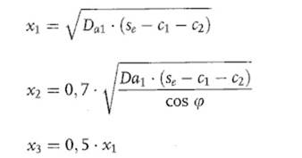
with se = required wall
thickness within the decay area. Within the decay range, the required wall
thickness is given in 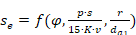 for converging conical
shells is given in Figures 3.1 to 3.7 of AD Leaflet B2 and for diverging
conical shells in Figure 3.8. Fig. 3.3 ( = 30°) and Fig. 3.6 ( = 60°) as well
as Fig. 3.8 are included in extracts for the exemplary treatment in Annex 30.
For intermediate values of the wall thicknesses can be interpolated linearly;
for intermediate values of r/Da, the respective interpolation equation given
must be applied. The wall thickness sl must at least correspond to
the wall thickness sg required outside the decay length, i.e. the designed wall
thickness of a tapered transition element must not be smaller than the
thickness of the smooth tapered shell determined for the corresponding loads.
for converging conical
shells is given in Figures 3.1 to 3.7 of AD Leaflet B2 and for diverging
conical shells in Figure 3.8. Fig. 3.3 ( = 30°) and Fig. 3.6 ( = 60°) as well
as Fig. 3.8 are included in extracts for the exemplary treatment in Annex 30.
For intermediate values of the wall thicknesses can be interpolated linearly;
for intermediate values of r/Da, the respective interpolation equation given
must be applied. The wall thickness sl must at least correspond to
the wall thickness sg required outside the decay length, i.e. the designed wall
thickness of a tapered transition element must not be smaller than the
thickness of the smooth tapered shell determined for the corresponding loads.
The calculation formulas for the corner joint between the tapered and cylindrical shells (corner joint) apply to a fully welded seam, welded on both sides.
According to Wagner,
cones with corner seam (r = 0) are only permissible for 30°(also ASME codes and
for lengths of the wefts of at least  . This restriction is
not included in the AD regulations.
. This restriction is
not included in the AD regulations.
In the edge area (within the decay area), there must be no cutouts or other interference points (except welds). Outside the edge area, circular cutouts may be present without or with reinforcement. In the case of loading by external pressure, proof must be provided to limit permanent strains and to demonstrate sufficient stability.
For large cone shells consisting of plates of different thicknesses or with different strength properties, calculations must be performed separately for each type of plate.