Variable list
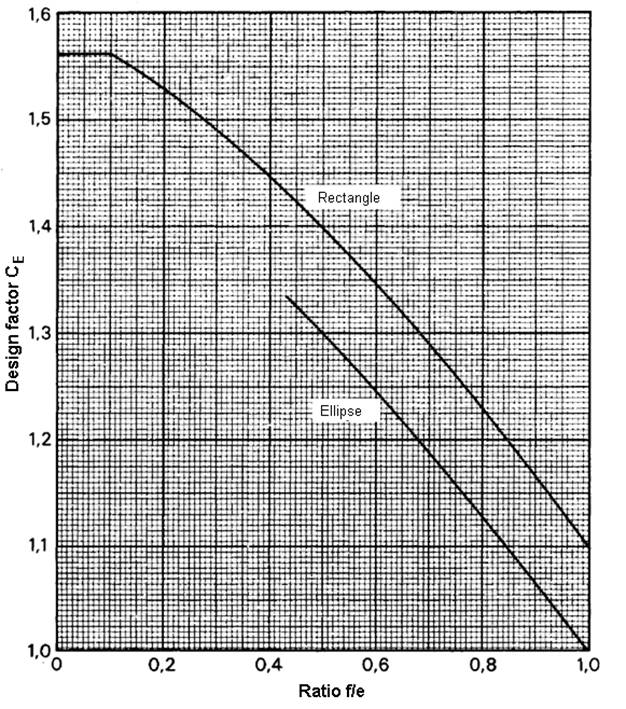
Fig 2 Design factor CE of rectangular or oval plates
Type A
|
d |
Inside diameter of opening |
|
|
D1 |
Design diameter |
|
|
f |
Narrow side of elliptical end |
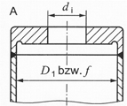
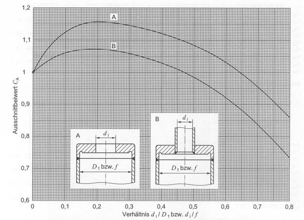
Fig. 21 – Design factor CA for flat ends and plates without additional boundary
moment
Type B
|
d |
Inside diameter of opening |
|
|
D1 |
Design diameter |
|
|
f |
Narrow side of elliptical end |
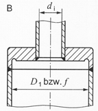
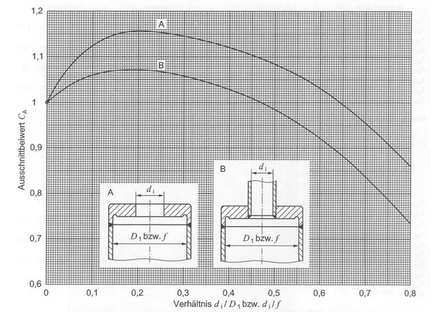
Fig. 21 – Design factor CA for flat ends and plates without additional boundary
moment
Type A
|
d |
Inside diameter of opening |
|
|
dt |
Bolt circle diameter |
|
|
dD |
Gasket diameter |
|
|
f |
Narrow side of elliptical end |
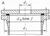
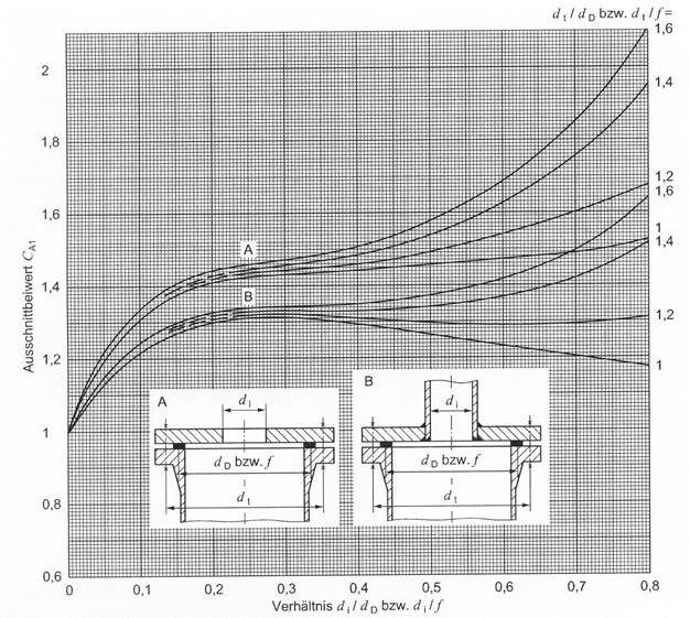
Fig. 22 – Design factor CA1 for plates with additional boundary moment
Type B
|
d |
Inside diameter of opening |
|
|
dt |
Bolt circle diameter |
|
|
dD |
Gasket diameter |
|
|
f |
Narrow side of elliptical end |
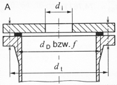
Fig. 22 – Design factor CA1 for plates with additional boundary moment
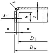
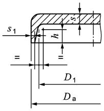
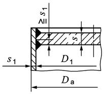
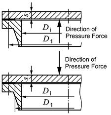
Table 1 – Design factors of flat ends without additional boundary moment
|
Type |
Conditions |
Design |
||||||||||||||
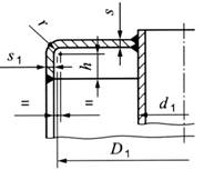
a) flanged flat end
|
1. Knuckle radius:
2. Cylindrical part: h ≥ 3,5s (Please note conditions from section 6.1.1!) |
0,30 |
||||||||||||||
|
b) forged or pressed flat end
|
1. Knuckle radius However at least 8 mm. 2. Cylindrical part h ≥ s (Please note conditions from section 6.1.1!) |
0,35 |
||||||||||||||
|
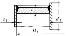
c) flat plate welded into the shell from both sides
|
Plate thickness |
|
||||||||||||||
|
s ≤ 3 s1 |
0,35 |
|||||||||||||||
|
s > 3 s1 |
0,40 |
|||||||||||||||

|
Type |
Conditions |
Design |
|
d) bolted flat plate with full face gasket
|
D1 ≥ Di |
0,35 |
|
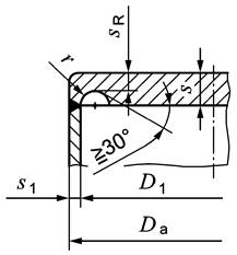
e) flat plate with stress-relieve groove 1)
s1= Final wall thickness of cylindrical part of the end connected to the shell. |
1. Residual wall thickness in the groove:
not less than 5 mm and with Da > 1,2 D1 sR ≤ 0,77 s1 2. Groove radius: r ≥ 0,2 s, however not less than 5 mm and 3. Only killed steels may be utilized. When plate material is employed over an area of at least 3 s1 in the weld zone there must be no evidence of material discontinuities in the plate 2). 4. For special loads e.g. creep structure strength, this type is inappropriate without extra proof. 5. Please note conditions from section 6.1.1! |
0,40 |
|
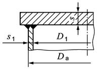
f) flat plate welded onto the shell from both sides
|
Plate thickness: |
|
|
s ≤ 3 s1 |
0,40 |
|
|
s > 3 s1 |
0,45 |
|
|
Only killed steels may be utilized. When plate material is employed over an area of at least 3 s1 in the weld zone there must be no evidence of material discontinuities in the plate 2). |
|
|
|
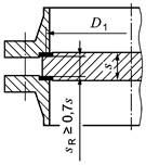
g) simply supported flat plate
|
Residual wall thickness at the gasket circle or at the grooves sR ≥ 0,7 s |
0,40 |

|
Type |
Conditions |
Design |
|
h) flat plate welded into the shell from one side only
|
Plate thickness: |
|
|
s ≤ 3 s1 |
0,45 |
|
|
s > 3 s1 |
0,50 |
|
|
i) partially-welded flat plate
|
Plate thickness: |
|
|
s ≤ 3 s1 |
0,45 |
|
|
s > 3 s1 Conditions for a: a ≥ 0,5 s and a ≥ 1,4 s1 Df /D1 ≥ 0,7 |
0,50 |
|
|
k) flat plate attached from the external side
|
1. Residual plate thickness at gasket
circle: 2. Soft gasket |
1,25 |
|
l) flat plate attached from the internal side
|
Residual wall thickness at gasket circle: sR ≥ 0,7 s |
0,45 |
|
1) Stress-relieve grooves with different cross section may be more effective in reducing stresses and are acceptable if appropriate evidence is produced. 2) The test for non-doubling in the area of the weld seam is carried out for ferritic materials according to DIN EN 10160, quality class E 3, and for austenitic materials according to DIN EN 10307, quality class E 3. |
||
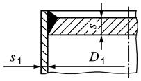
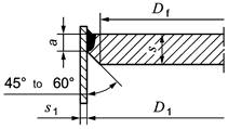
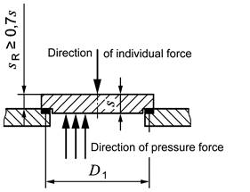
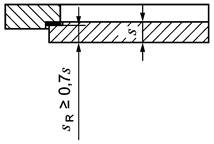
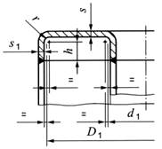
Table 2 – Design factors of circular flat ends and plates with a central stay bolt or tube
|
Type |
Conditions |
Design |
||||||||||||||
Flanged flat end a) with inward flange
or b) with protruding stay
|
1. Knuckle radius:
2. Cylindrical part: h ≥ 3,5s (Please note conditions from section 6.5.1!)
|
0,25 |
||||||||||||||
|
c) flat plate welded into the shell from both sides with protruding stay
|
Plate thickness |
|
||||||||||||||
|
s ≤ 3 s1 |
0,30 |
|||||||||||||||
|
s > 3 s1 |
0,35 |
|||||||||||||||
|
d) flat plate welded into the shell from one side with protruding stay
|
Plate thickness |
|
||||||||||||||
|
s ≤ 3 s1 |
0,40 |
|||||||||||||||
|
s > 3 s1 |
0,45 |
|||||||||||||||

|
Type of stay bolts |
Design factor C3 |
|
Screwed and riveted or |
0,47 |
|
Screwed with nuts on both ends |
0,44 |
|
Welded |
0,40 |
|
|
|
|
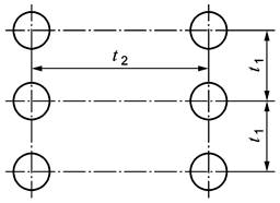
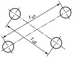
Uniformly distributed stays |
Irregularly distributed stays |
|
|
|
|
Uniformly distributed stays |
Irregularly distributed stays |
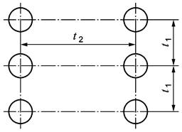
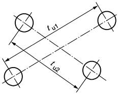
s. Table 1 – Design factors of flat ends without additional boundary moment
s. Table 2 – Design factors of circular flat ends and plates with a central stay bolt or tube