Module B7
Gasket database of Münster University of Applied Sciences on the Internet (external link)
On this homepage, created and maintained by the Münster University of Applied Sciences, Sealing Technology Research Department, you will find current EN13555 characteristic values for sealing materials of the EN 1514 and EN 12560 standard series. The content of this website is updated at regular intervals (on the second Wednesday of each month).
The database was developed in close cooperation with the gasket manufacturing industry. The characteristic values are either determined by testing institutes or, in the case of in-house tests, randomly tested in order to maintain the necessary objectivity and reliability of the characteristic values.

When considering the strength of a flange connection consisting of flanges, bolts and gasket, the individual parts must always be considered in relation to each other, taking into account the conditions prevailing in the various states (installation state, start-up state, operating state). The forces and deformations occurring in the individual conditions can be illustrated by the simplified stress diagram in Fig. 12.1, which shows the spring conditions.

Fig. 12.1 Tensioning diagram (simplified representation)
By tightening the bolts with the force FSo
= FDo, the gasket is brought into close contact with the bearing
surfaces. In addition to plastic deformation, the gasket undergoes elastic
compression ΔDo, while the two flanges bend elastically by 2
ΔFl between the gasket circle with diameter dD and the bolt circle with
diameter dt, and the bolts undergo a change in length ΔS. The spring
characteristics applicable to the installed condition are drawn out thinly in Fig.
12.1.
In the start-up condition, when the internal pressure p is released, corresponding to an internal pressure force Fp = p * π * d2 /4, the bolt force increases to the value FSl in the case of a cold connection and the force on the gasket decreases to FDl (dashed). In hot joints, due to the difference in heating of flanges and bolts, the strain difference ΔWA occurs, causing further stress, so that the bolt force increases to FS2 and the gasket force increases to FD2 (dashed-dotted).
If the standing force FDθ, which the gasket is capable of withstanding over a longer period of time, especially at higher temperatures, is lower than FD2, the gasket creeps over time by the amount ΔD' until the sealing force has reached the value FD3 = FDθ. During this process, the bolt force drops to FS3. With the temperature equalization between bolts and flanges, the thermal expansion difference decreases to ΔWB in the operating condition, which causes relaxation again (strongly extended). The force FD4 remaining on the gasket must be greater than the force FDB required to maintain the seal in operation.
From: Schwaigerer, S.: Die Berechnung der Flanschverbindungen im Behälter- und Rohrleitungsbau. Z. VDI 96 (1954) 7.
Due to the twist of the flange leaf, no additional bolt force builds up in contrast to flange leaves that lie flat. Increasing the bolt force with the lever arm ratio Y1/Y2 can be omitted for this connection.

If a special seal is used, additional information on the seal can be entered in the comments field.
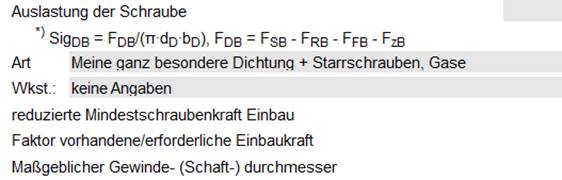
If the remark field is empty, the program will fill it with the default values.
Consideration of external shear forces and an external torsional moment by means of an increased tightening torque
In order to be able to transmit a transverse force Q (perpendicular to the pipe axis) and a torsional moment Mt by frictional engagement in the flange connection, an additional force FZ must act on the gasket if necessary.
FC amounts to:
aa) for laterally displaceable flanges in which transverse forces can only be transmitted by frictional engagement

ab) for flanges that cannot be displaced laterally, where transverse forces are transmitted by form fit

If equations (A 2.8-10) or (A 2.8-11) result in an FZ > 0, this force must be added to the required operating sealing force according to equation (A 2.8-5).
|
Hint: Metal O-ring seals are not suitable for absorbing transverse forces and torsional moments due to frictional engagement. |
If no other test results are available, the coefficients of friction are to be used as follows:
= 0.1 for graphite coated gaskets
= 0.15 for metallic supports with smooth surface
= 0.25 for It seals
|
Formula sign |
Calculation variable |
Unit |
|
FZ |
Axial tensile force for the transmission of transverse forces and torsional moments in frictional engagement at operating condition |
N |
|
FDB |
required sealing force for the design condition |
N |
|
MB |
Bending moment in the tube |
N mm |
|
Mt |
Torsional moment in the tube |
N mm |
|
dD |
Medium seal diameter |
mm |
|
dt |
Bolt circle diameter |
mm |
|
|
Friction value |
- |
The force play in a flange connection, as it prevails in the various operating conditions, can be illustrated by its stress diagram. The flange connection is seen as a spring system in a flow of forces, consisting of the bolts, the two flanges and the gasket.
|
Figure 3.50 Development of the bracing diagram for pipeline flange connections
a) Flange connection without gasket and very stiff flanges. Thus elongation of the bolts alone
b) Flanged joint without gasket with elongation of bolts and compression of flanges
c) Flange connection without gasket with bolts and flange leaves as stressed parts, compression of flanges neglected
d) Flange connection with gasket, in which the bolts as well as the flange sheets act as stressed parts and the gasket acts as a stressed part. Upsetting of the flanges neglected |
|

In the stress diagram, in which the spring characteristics of the stressed and tensioned parts of a connection lying in a closed flux of forces are plotted, the elastic deformation changes in the direction of the pipe axis are plotted on the abscissa and the corresponding forces are plotted on the ordinate, with the force deformation ratios of bolts plus flanges usually being shown on one side and that of the gasket on the other (Fig. 3.50). Since the forces change in each case from the installation state through the start-up state to continuous operation, the states mentioned must be recorded in detail by the corresponding stress lines.
|
The tension diagram represents the interplay of forces between tensioned and tensioned parts. |
When the n bolts are tightened with the force Fs, each bolt (Fig. 3.51 s. deflection of a loose flange with collar) undergoes elongation D S, the two flanges deflect between bolt and gasket circles by the amount 2-D Fl, while the gasket is elastically compressed by D D .
|
|

with
Ls = clamping lengths of the screws
ds = for expansion screws the shaft diameter ds
ds = for solid shaft screws, the mean thread diameter
|
|

If, for flanges with tapered neck
hA > hF , then h' = hA
If hA < hF, then:

For weld-on bandages:

|
|

No significant deflection is to be expected in flanges with flat gaskets bearing up to the outer edge or with flange sheets lying flush.

The elastic recovery for flat gaskets is calculated as:
|
|

For It gaskets ED " 1500 N/mm²
For metal/soft-material gaskets ED " 4000 N/mm²
The springback of metallic gaskets can be neglected compared to the springback of bolts and flanges.
When the flange connection is put into operation, on the one hand, due to the uniformly assumed heating of the entire connection to temperature, there is a relief of the bolt force on:

as well as a change of the screw elongation to

On the other hand, the moment of changes due to the internal pressure becoming effective:

in:

whereby the change of the deflection of a flange in:

is connected

During installation, the screws must be tightened with the screw force FS0 according to the required pre-press force FDV of the gasket.
If the internal pressure p is released without a change in temperature, the internal pressure force Fp' causes the bolt force to increase to the value FS1, and the sealing force to decrease to FD1. The slope of the spring characteristic curve of bolts and flanges changes in proportion to the external moments.
If, during startup, a temperature difference occurs between the bolts and the fluff corresponding to the elongation difference D WA, additional tensioning of the joint occurs, with the bolt force FS2, and the sealing force increasing to FD2. The slope of the spring curve decreases as the modulus of elasticity changes with temperature.
Usually, the gasket is unable to absorb the increased pressure when exposed to heat. It begins to creep, whereby the joint relaxes until, after a creep distance of D D', the force FD that the gasket can withstand is reached. At the same time as the gasket creeps, however, temperature equalization also takes place between the bolts and flanges at a residual value D WB. The bolt force reaches the value FS3.
During startup, when the pressure is removed below operating temperature, the pressure on the seal increases, resulting in renewed creep until the bolt force reaches the standing force of the seal FD. If the internal pressure is now applied again, this is followed by relaxation at the seal on FD4. In order for the joint to remain tight, it must be required that the sealing force FD4 is greater than the operating sealing force FDB required to keep the joint tight during operation. In the case of soft seals, it is often necessary to retighten the joint in order to achieve this condition.
If tensile forces are present in the pipeline, the sealing force decreases and the stress diagram changes as shown in Fig. 3.53.

From: Walter Wagner, Strength calculations in apparatus and pipeline engineering, 6th ed.
by Theo von Reth, Mannheim
In the case of rectangular flanges on pressure vessels, an agreement on the calculation is necessary between the manufacturer and the supervisor, for which this article is intended as a suggestion.
The section modulus of a round flange is composed of the section modulus of the flange edge, which counteracts torsion, and the section modulus of the flange neck, which counteracts bending. In the usual designs, the section modulus of the flange edge is much greater than that of the flange neck. This also explains why a loose flange only needs to be slightly thicker than a weld-on flange of the same diameter.
In a rectangular flange, the section modulus of the flange edge in the center of the long rectangular side is negligibly small. Due to the occurring torque, caused by the internal pressure and the bolt force counteracting it, the flange edge experiences a stress on torsion. With increasing distance of the force application from the clamping, the plastic deformation becomes so great that the gasket no longer bears. At this point, therefore, the section modulus of the flange neck must be large enough to ensure that the deformation of the flange does not exceed that required for seal retention. At higher pressures, this results in wall thicknesses that lead to impractical designs.
When continuous gaskets are used, no twisting of the flange occurs, but they are suitable for low pressures. Above about 6 atü, however, the force required to pre-deform them becomes so great that other solutions must be sought. One could provide the flange edge on the outside with a strip about as thick as the gasket. This would ensure that it can no longer twist. On the other hand, however, the bolt force would be increased in proportion to the lever arms, i.e., practically about doubled. The design would require screw diameters that could no longer be accommodated on the available surface at higher pressures.
One way of increasing the section modulus of the flange neck is to weld beams on the inside of the flange or to weld ribs between the flange edge and the vessel wall. However, this results in additional stress peaks, the calculation of which requires a time expenditure that is not economically justifiable in relation to the design of the vessel part. Welding in tie rods that counteract the bolt force at an angle of 90° is also problematic, since the change in length of the tie rod must be exactly the same as the change in length of the bolts.
The simplest solution is to have the rectangular flanges rest metallically on the mating flange or tube plate and to accommodate the seal in a groove. (e.g. O-rings); for higher temperatures, the "metal O-ring seal" can be used, which has proven its worth in American aerospace and nuclear technology.
With this design, the flange neck is only subjected to tensile stress and no torsion occurs in the flange edge, only bending. This means much smaller wall thicknesses than with a flange stressed in torsion. The bolt forces also remain somewhat smaller, since the predeformation for the proposed gaskets is smaller than for the usual flat gaskets. A further advantage occurs with heat exchangers, since in this case the fixed flange counteracts deflection of the tube plate.
The following equation can be used to calculate the thickness of the flange edge for this design. The designations are taken from DIN 2505.

t = distance between the screws
w = distance from the center of the gasket to the centerline of the flange (referred to the small side of the rectangle)
p = pressure in bar

Techn. Monitor. 8 (1967) No. 12 December


From: Esser, Josef Illgner, K.-H.; Schrauben Vademecum; 9th edition 2001