General Operation
The proof of adjacent nozzles is only valid if a single nozzle proof has been performed for all adjacent nozzles!
Calculating a substitute diameter
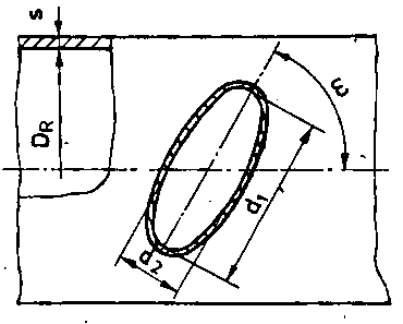

dR substitue diameter
cS sum of all allowances in shell
For determining the reinforcement of the opening we recommend the following procedure:
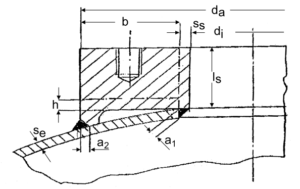
The block flange is divided in:
·
a fictitious nozzle with the dimensions:
di = Diameter of opening
ss = fictitious nozzle wall: ss = a1
ls = fictitious nozzle length:

· and a fictitious reinforcement pad
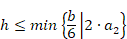
h = fictitious
height of pad:
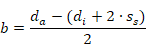
b = fictitious width of pad:
If the allowable stress of the block flange is lower than the allowable stress of the shell, you have to reduce the reinforcement areas using the ratio of the allowable stresses.
The procedure is the same as recommended for set-on block flanges (s. Set-on block flange / reinforcement ring), whereas as fictitious nozzle wall the value:

Can be used.
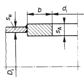
Fig. 3a - Set-in reinforcement or block flange
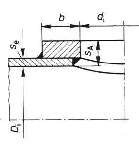
Fig. 3b – Block flange
|
|
|
|
|
Type a) |
Type b) |
Type c) |
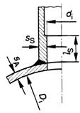
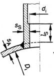
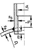
Fig. 5 - Tubular reinforced opening
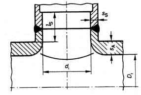
Fig. 6 - Extruded opening
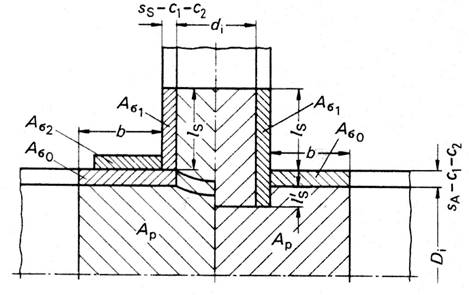
Fig. 9 - Calculation scheme for cylindrical shell
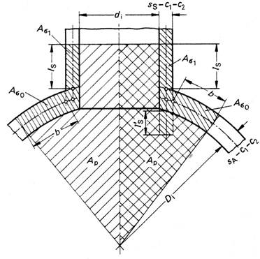
Fig. 10 - Calculation scheme for spherical shell
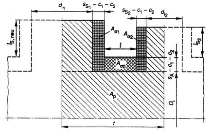
Fig. 11 - Adjacent openings in longitudinal direction of cylinder
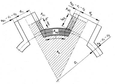
Fig. 12 - Adjacent openings in circumferential direction of cylinder or in spherical shells
|
|
|
|
Type a) |
Type b) |
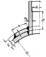
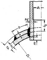
Fig. 13 - Disc and tubular reinforcement