Variables
Please enter here the inside diameter of the bearing ply.
If there is an additional inner protective ply it is not considered for entering Db.
If a consideration is required the program does so internally.
Test conditions
1. The allowable nominal design stress and the modulus of elasticity are determined at a temperature of 20 °C.
2. Testing is done in neutral position.
As a consequence,
· set all deflections and movements to 0
· there is no pre-stressing load
· there is no calculation of allowable load cycles.
· as the movement e=0, there is no calculation of stresses due to deflection (S5 and S6)
· this has to be taken into account when checking the strength conditions.
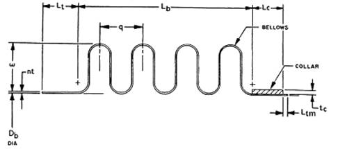
Fig. 4.13: Unreinforced bellows
Valid for reinforced and reinforced bellows.
ri is the arithmetic average from rir and ric (see Figure 4.13a; ri = (rir+ric)/2
Please note that you have to specify this value without considering an inner or outer protective ply and it is only valid for the bearing ply.
rm is calculated internally as the mean radius of the bearing bellows convolutions, rm=ri+np1*t1/2.
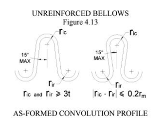
Fig. 4.13a
The allowable stress is not determined automatically. You have to enter it manually for the selected load case.
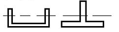
TABLE III – Shape Factors
|
Shape |
|
|
Solid Rectangle
|
Ks = 1.5 |
|
Solid Cylinder
|
Ks = 1.7 |
|
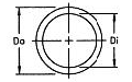
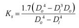
Hollow Cylinder
|
|
|
Hollow rectangle, beam, Channel
|
|
|
Beam, Tee
|
|
|
Channel, Tee
|
Ks = 1.5 or calculated value |


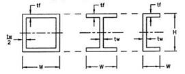
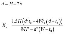
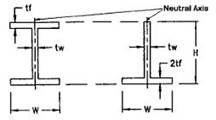
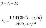
You can select from three methods of forming. They have the following effects:
· - roll forming: Kf=1; tp=t*SQRT(Db/Dm)
· - with expanding mandrel: Kf=1; tp=t
· - hydraulic or pneumatic tube forming: Kf=0,6; tp=t*SQRT(Db/Dm)
The calculation of the existing stresses is only performed with consideration of the bearing ply.
The following choice
· Without additional ply (spring rate)
· With additional ply (spring rate)
is only required for calculation of the spring rate.
Regardless of the selected calculation method, the calculation is always performed like this:
· For calculating the stresses due to pressure S1, S‘1, S‘‘1, S‘‘‘1, S2, S‘2, S‘‘2, S3, S4, only the bearing ply is considered. This might result in slightly higher stresses, but then you are on the safe side.
· For calculating the stresses due to movements S5 and S6, also only the bearing ply is considered. There is no check of the stresses of the inner or outer protective ply. This does not matter for the pressure capacity of the bellows. The behavior of the inner and outer ply is not considered for calculating the number of allowable load cycles.
Determining the spring rate of the bellows without considering the inner or outer ply, might result in a value, which might be too low.
The bellows would be more rigid than calculated and the results would be ion the unsafe side.
That is why we have a program feature to consider an inner and/or outer ply for calculating the spring rate.
The allowable pressure for the limit of the column stability and the in-plane stability is only calculated with considering the bearing ply only, regardless of the selected calculation method.
Special Case:
Assumed that the bearing ply consists of multiple plies, made of 1.4541. The inner protective ply is made of 1.4571 as a corrosion protection. As long as the wall thickness of the single plies are identical, the protective ply might be added to the bearing ply, but this is a case-by-case decision.
Entering the movements
You can enter an operating load case and a corresponding pre-stressing load case.
It is considered that lateral movements and angular movements have not to be in the same plane. They are added vectorially.
It is assumed, that all movements are in x-y plane. That is why movements in x-z plane are set to 0 by default.
If the movements are in one plane, the EJMA descriptions are as follows:
x-y_LF1 -> y_LF1 (in mm)
θxy_LF1 -> θ_LF1 (Input in °, Conversion in Radiant is done by the program internally)
The x direction is the axis of the bellows in its original form.
When entering the movements, please note the following:
· All movements, of the operating load case (load case 1) and of the pre-stressing load case (load case 2) are always referring to the bellows in neutral position.
· Enter values for x axial movements signed!
+ x means elongation
- x means compression
At all other movements the algebraic sign is ignored.
With universal bellows, the angle of rotation of the intermediate piece is displayed.
Additionally the movements, caused by the dead load of the intermediate piece can be determined. These movements are not considered by the program. If you want to take these movements into account, you have to adjust your input values for the movements.
Entering the pre-stressing case simultaneously, is required for calculating the total movements between pre-stressing load case and operating load case.
With the total movements, the stresses S5 and S6 are determined. These stresses are used for calculating ST and furthermore for calculating the number of allowable load cycles.
This value is only required for toroidal bellows, if there is an internal attachment of the bellows.
If there is not, enter tpe as 0. This sets the circumferential membrane stress of the pipe to zero.
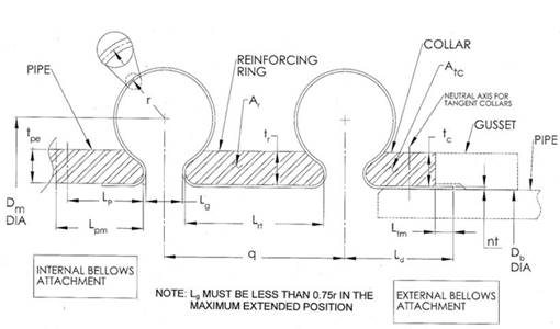
Fig. 4.15: Toroidal bellows
Ld is the maximum length from the attachment weld at the cylindrical end of the bellows to the center of the first convolution for externally attached bellows.
This value is required for unreinforced bellows and toroidal bellows. In case of an internal attachment of the bellows, please enter Ld=0. This sets the circumferential membrane stress of the cylindrical bellows end S1 to zero.
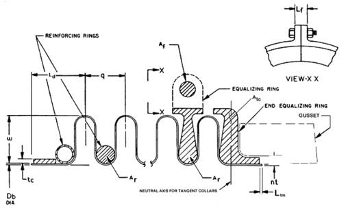
Fig. 4.44: Reinforced bellows
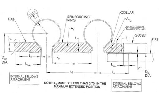
Fig. 4.15: Toroidal bellows
Fig. 4.15: Torusbalg
R is the mean radius of the bearing ply, without considering the inner or outer protective ply.
|
|
Manufacturing Constants |
|
|
|
Material Class |
c |
b |
Material Grades, UNS (EN) |
|
1 |
1.86E+06 |
54000 |
Austenitic stainless steels S3xxxx (1.43xx to 1.49xx) Special nickel-chromium alloys N08800 (1.4876) High heat or corrosion resistant nickel alloys N08810 (1.4958), N06600 (2.4816), N04400 (2.4360), N08811 (1.4949) |
|
2 |
2.33E+06 |
67500 |
Corrosion resistant nickel-molybdenum-chromium alloys N06455 (2.4610), N10276 (2.4819), N08825 (2.4858) |
|
3 |
2.70E+06 |
78300 |
High strength nickel-chromium alloys N06625 (2.4856) |
Fig. 4.20

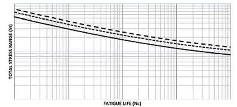
________ CLASS 1
------------- CLASS 2
- - - - - - - - CLASS 3
· These equations are based on average curves but also allow for the Inclusion of factor fc, for modification to the lower bound of the curve and also to allow for the addition of a safety factor to ensure minimum fatigue life required for pressure and fluid containment applications such as ASME and PED.
· Unless otherwise indicated by specification, a traditional value, fc =1 is used when providing EJMA calculations.
· AlI calculations for fatigue in accordance with this section shalt indicate the value used for fc
· These curves are intended to predict fatigue life for as-formed or annealed bellows at temperatures below the bellows material creep range.
· They are considered valid in the range of 10E+02 to 10E+06 cycles, due to the limited data available for the very low and very high cyclic ranges.