EN18-e
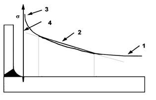
Key:
1 Nominal stress
2 Structural stress
3 Notch stress
4 Extrapolation to give structural stress at potential crack initiation site.
Fig. 18-1 — Distribution of nominal, structural and notch stress at a structural discontinuity
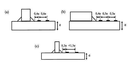
Fig. 18-3 - Extrapolation to obtain structural stress from FEA or strain gauge results (in Annex N)
Locations of stresses for determination of structural stress by extrapolation to point of stress concentration (weld toe in this case):
a) low bending stress component, gauge length ≤ 0,2e, linear extrapolation;
b) high bending stress component, stiff elastic foundation, gauge length ≤ 0,2e, quadratic extrapolation;
c) gauge length > 0,2e, linear extrapolation
where "gauge length" refers to size of strain gauge or FE mesh.
(a) Typical variation with time of the structural principal stresses
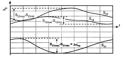
(b) Variation with time of the principal stress differences and the resulting Δσeq
Fig. 18-4 - Typical example of stress variation when the principal stress directions remain constant
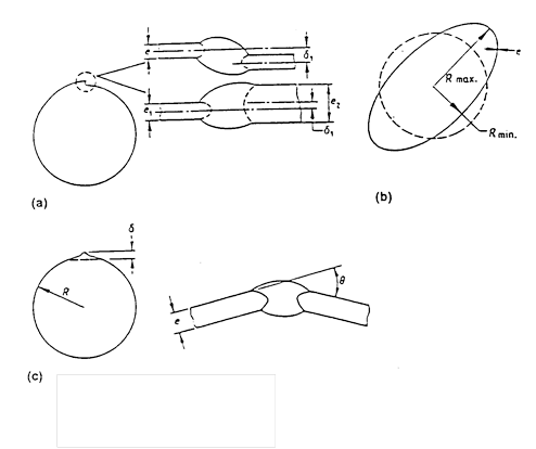
(a) Axial misalignment
(b) Ovality
(c) Angular distortion
Figure 18-10 — Deviations from design shape at seam welds
Table 18-4 — Class of weld details for use with structural equivalent stress range a) - Seam welds
|
Detail No. |
Joint type |
Sketch of detail |
Comments |
Class |
|
|
Testing group |
Testing group |
||||
|
1.1 |
Full penetration butt weld flush ground, including weld repairs |
Fatigue cracks usually initiate at weld flaws |
Weld to be proved free from surface-breaking flaws and significant sub-surface flaws (see EN 13445-5:2014) by non-destructive testing. Use fe instead of few. |
90 |
71 |
|
1.2 |
Full penetration butt weld made from both sides or from one side on to consumable insert or temporary nonfusible backing |
1:3 |
Weld to be proved free from significant flaws (see EN 13445--5:2014) by nondestructive testing and, for welds made from one side, full penetration*. |
80 |
63 |
|
1.3 |
1:3 e |
Weld to be
proved free from significant flaws by nondestructive testing Effect of centre-line offset to be included in calculated stress*. |
80 |
63 |
|
|
1.4 |
|
Weld to be proved free from significant flaws (see EN 13445-5:2014) by nondestructive testing |
|
|
|
|
a £ 30° |
80 |
63 |
|||
|
a > 30° |
71 |
56 |
|||
|
*In case of misalignment, see 18.10.4. |
|||||






Table 18-4 — Class of weld details for use with structural equivalent stress range a) - Seam welds
|
Detail No. |
Joint type |
Sketch of detail |
Comments |
Class |
|
|
Testing group |
Testing group |
||||
|
1.5 |
Full penetration butt welds made from one side without backing |
|
If full penetration can be assured*. |
63 |
40 |
|
If inside cannot be visually inspected and full penetration cannot be assured*. |
40 |
40 |
|||
|
1.6 |
Full penetration butt welds made from one side onto permanent backing. |
|
Circumferential seams only (see 5.7) Minimum throat = shell thickness |
|
|
|
Weld root pass inspected to ensure full fusion to backing. |
56
|
40 |
|||
|
Single pass weld. |
40 |
40 |
|||
|
1.7 |
Joggle joint |
|
Circumferential seams only (see 5.7) Minimum throat = shell thickness. |
|
|
|
Weld root pass inspected to ensure full fusion to backing. |
56 |
40 |
|||
|
Single pass weld. |
40 |
40
|
|||
|
*In case of misalignment, see 18.10.4. |
|||||



Table 18-4 — Class of weld details for use with structural equivalent stress range
b) — Shell to head or tubesheet
|
Detail No. |
Joint type |
Sketch of detail |
Comments |
Class |
||||||
|
Testing group |
Testing group |
|||||||||
|
2.1 |
Welded-on head |
|
Head plate shall have adequate through-thickness properties to resist lamellar tearing. |
|
|
|||||
|
(a)
|
Full penetration welds made from both sides (detail a): |
|
|
|||||||
|
- as-welded |
71 |
63 |
||||||||
|
- weld toes dressed |
80 |
63 |
||||||||
|
(b)
|
Partial penetration welds made from both sides (detail b): |
|
|
|||||||
|
- fatigue cracking in weld* |
32 |
32 |
||||||||
|
- fatigue cracking in shell from weld toe. |
63 |
63 |
||||||||
|
(c)
|
Full penetration welds made from one side without back-up weld (detail c): |
|
|
|||||||
|
- if the inside weld can be visually inspected and is proved to be free from overlap or root concavity. |
63 |
40 |
||||||||
|
- if the inside cannot be visually inspected and full penetration cannot be assured. |
40 |
40 |
||||||||
|
2.2 |
Welded-on head with relief groove |
|
Weld to be proved free from significant flaws (see EN 13445-5:2014) by NDT. |
|
|
|||||
|
Full penetration welds made from both sides, or from one side with the root pass ground flush. |
80 |
63 |
||||||||
|
Full penetration welds made from one side: |
|
|
||||||||
|
- if the inside weld can be visually inspected and is proved to be free from weld overlap and root concavity. |
63 |
40 |
||||||||
|
- if the inside cannot be visually inspected. |
40 |
40 |
||||||||
|
*To be considered only if weld throat < 0,8 x shell thickness |
||||||||||
|
2.3 |
Set-in head |
(a)
|
Full or partial penetration welds made from both sides (detail a). (Refers to fatigue cracking from weld toe in shell) : |
|
|
|||||
|
- as-welded |
71 |
63 |
||||||||
|
- weld toes dressed (see 18.10.2.2). |
80 |
63 |
||||||||
|
(b)
|
Partial penetration welds made from both sides (detail b): |
|
|
|||||||
|
- refers to fatigue cracking in weld, based on weld throat stress range. |
32 |
32 |
||||||||
|
- weld throat ≥ 0,8 x head thickness. |
63 |
63 |
||||||||
|
(c)
|
Full penetration weld made from one side without back-up weld (detail c): |
|
|
|||||||
|
- if the inside weld can be visually inspected and is proved to be free from overlap or root concavity. |
63 |
40 |
||||||||
|
- if the inside cannot be visually inspected. |
40 |
40 |
||||||||







Table 18-4 — Class of weld details for use with structural equivalent stress range
c) — Branch connections
|
Detail No. |
Joint type |
Sketch of detail |
Comments |
Class |
|
|
Testing group |
Testing group |
||||
|
3.1 |
Crotch corner |
1 Crack radiates from corner into piece, sketches show plane of crack. |
Assessment by the method for unwelded parts is the normal approach. However, simplified assessment using class 100 according to Annex Q is allowed.
Use fe instead of few |
100 |
100 |
|
3.2 |
Weld toe in shell |
|
Full penetration welds: |
|
|
|
- as welded |
71 |
63 |
|||
|
-
weld toes dressed |
80 |
63 |
|||
|
Partial penetration welds: |
|
|
|||
|
- weld throat ≥ 0,8 x thinner thickness of connecting walls, as welded |
63 |
63 |
|||
|
- weld throat < 0,8 x thinner thickness of connecting walls |
32 |
32 |
|||
|
-
weld toes dressed |
71 |
63 |
|||
|
3.3 |
Stressed weld metal |
|
Fillet and partial penetration welds. |
32 |
32 |
|
3.4 |
Weld toe in branch |
|
- As-welded. |
71 |
63 |
|
- Weld toes dressed en = branch thickness in Equation (18.10-6). |
80 |
63 |
|||






Table 18-4 — Class of weld details for use with structural equivalent stress range
d) Jackets
|
Detail No. |
Joint type |
Sketch of detail |
Comments |
Class |
|
|
Testing group |
Testing group |
||||
|
4.1 |
Jacket connection weld with shaped sealer ring |
|
Full penetration weld to be proved free from significant flaws (see EN 13445-5:2014) by non-destructive testing |
|
|
|
Welded from one side: |
|
|
|||
|
- multi-pass weld with root pass inspected to ensure full fusion; |
63 |
40 |
|||
|
- single pass weld. |
40 |
40 |
|||
|
Welded from both sides or from one side with back-up weld. |
71 |
56 |
|||


Table 18-4 — Class of weld details for use with structural equivalent stress range
e) — Attachments
|
Detail No. |
Joint type |
Sketch of detail |
Comments |
Class |
|
|
Structural equivalent stress |
Nominal equivalent stress |
||||
|
Testing group |
Testing group |
||||
|
5.1 |
Attachment of any shape with an edge fillet or bevel buttwelded to the surface of a stressed member, with welds continuous around the ends or not |
|
For details with welds continuous around ends, one class increase if weld toes dressed (see 18.10.2.2) |
|
|
|
L ≤ 160 mm, t ≤ 55 mm |
71 |
56 |
|||
|
L > 160 mm |
71 |
50 |
|||
|
5.2 |
Attachments of any shape with surface in contact with stressed member, with welds continuous around ends or not |
|
For details with welds continuous around ends, one class increase if weld toes dressed (see 18.10.2.2) |
|
|
|
L ≤ 160 mm, W ≤ 55 mm |
71 |
56 |
|||
|
L > 160 mm, W ≤ 55 mm |
71 |
50 |
|||
|
L > 160 mm, W ≤ 55 mm |
71 |
45 |
|||
|
5.3 |
Continuous stiffener |
|
For full penetration welds, one class increase if weld toes dressed (see 18.10.2.2) |
|
|
|
t £ 55mm |
71 |
56 |
|||
|
t > 55mm |
71 |
50 |
|||
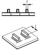
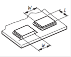
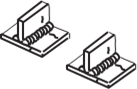
Table 18-4 — Class of weld details for use with structural equivalent stress range (continued)
f) Supports
|
Detail No. |
Joint type |
Sketch of detail |
Comments |
Class |
|
|
Testing group |
Testing group |
||||
|
6.1 |
Support on either horizontal or vertical vessel |
1 Fillet welded to vessel all round 2 Backing plate |
As-welded. |
71 |
71 |
|
Weld toe in shell dressed |
80 |
80 |
|||
|
6.2 |
Trunnion support |
1 Backing plate |
As-welded. |
71 |
71 |
|
Weld toe in shell dressed |
80 |
80 |
|||
|
6.3 |
Saddle support |
1 Fillet welded to vessel all round |
As-welded. |
71 |
71 |
|
Weld toe in shell dressed |
80 |
80 |
|||
|
6.4 |
Skirt support |
|
Welded from both sides: |
|
|
|
as-welded; |
71 |
71 |
|||
|
weld toe in shell dressed |
80 |
80 |
|||
|
Welded from one side |
56 |
56 |
|||
|
6.5 |
Leg support (with or without reinforcing pad) with fillet weld to vessel continuous all around. |
|
|
71 |
71 |
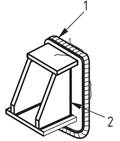
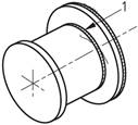
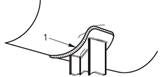
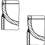

Table 18-4 — Class of weld details for use with structural equivalent stress range
g) Flanges and pads
|
Detail No. |
Joint type |
Sketch of detail |
Comments |
Class |
|
|
Testing group |
Testing group |
||||
|
7.1 |
Full penetration butt welded neck flange or compensation flange with welding lug. |
|
Weld to be proved free from surface-breaking and significant sub-surface flaws (see EN 13445-5:2014) by nondestructive testing. |
|
|
|
Weld made from both sides or from one side with back-up weld or onto consumable insert or temporary backing. |
80 |
63 |
|||
|
Weld made from one side: |
|
|
|||
|
- if full penetration can be assured |
63 |
40 |
|||
|
- if the inside cannot be visually inspected |
40 |
40 |
|||
|
7.2 |
Welded flange |
|
Full penetration welds: |
|
|
|
- as-welded |
71 |
63 |
|||
|
- weld toe dressed |
80 |
63 |
|||
|
Partial penetration welds: |
|
|
|||
|
- weld throat ≥0,8 x shell thickness; |
63 |
63 |
|||
|
- weld throat < 0,8 x shell thickness. |
32 |
32 |
|||
|
7.3 |
Set-in flange or pad |
|
Full penetration weld: |
|
|
|
- as-welded |
71 |
63 |
|||
|
- weld toe dressed |
80 |
63 |
|||
|
Weld made from one side: |
|
|
|||
|
- if full penetration can be assured |
63 |
40 |
|||
|
- if the inside cannot be visually inspected |
40 |
40 |
|||
|
Fillet welded on both sides: |
|
|
|||
|
- weld throat ≥ 0,8 x shell thickness; |
63 |
32 |
|||
|
- weld throat < 0,8 x shell thickness. |
32 |
32 |
|||
|
7.4 |
Set-in flange or pad, welded from both sides |
|
- weld throat ≥ 0,8 x shell thickness; |
63 |
32 |
|
- weld throat < 0,8 x shell thickness. |
32 |
32 |
|||