FAQ
Flange dimensions in 1591
WTS -doubling of heat exchanger area due to fouling
AD 2000 B3 - Maximum diameter outside 0.6 Da
Module 25V contains DIN V2505 as option
Which quantities must be entered for heat exchanger trays with edge moment?
Permissible buckling force for tube plates in module B51
Load change calculation according to AD 2000 S1 from -1bar to 6bar
Why is the minimum bolt force FSB greater than (FRP + FFB + FDB ) ?
When must the bolt force FDV be reduced?
How to determine the bolt force (operation, installation)?
How to calculate cutouts in cones according to B9?
Calculation of cutouts, single nozzles on spherical body
Several cutouts in floors and slabs according to AD 2000 B5
What do I need to consider for cutouts in curved floors?
How are tanks designed for low temperatures?
B9 or B9N - block flanges
WRC, WRCK - Strong change in the occurring stress, with small change in wall thickness.
Different voltages at Probad and at WRC
Integrate the LV programs as background programs (libraries) in your own programs.
Negative values appear in the printout of the UG37 module.
Flange dimensions of standardized flanges are entered automatically the first time only
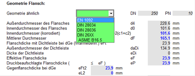
The module 1591 offers the possibility to fill in the flange dimensions of standardized flanges automatically (in the line "Geometry similar "). However, this is possible only at the first input, after that if I choose e.g. another nominal sizethe dimensions will not be adjusted.
Response:
It is intended to suppress the re-import of the geometry data, because many customers want to take over the geometry values but then want to change individual ones. These should then no longer be overwritten.
If you want to request a new nominal width, please enter it in the flange module itself, or change the value on the "Geometry similar..." mask to the new value and instead of pressing the "Enter key", perform a refresh by pressing the "F7 key".
Example:
The two fouling factors fi = 0.00025 m²-K/W and fa = 0.000085 m²-K/W together give a total fouling factor of
Rf = 0.000427 m²-K/W (Rf = fi -da/di +fa, the internal fouling factoris related to the external surface).
If Rf is converted into a heat transfer coefficient, the following value results: Alpha_f = 1/Rf = 2342 W/(m²-K).
In the present case, the heat transfer coefficients Alpha_i = 7773 W/(m²-K) and Alpha_a = 15947 W/(m²-K) are very large. However, since the heat transfer coefficient k is always smaller than the smallest of the heat transfer coefficients Alpha_i, Alpha_a, Alpha_f, the required area for this heat exchanger isdetermined by the fouling. Taking the fouling into account, the required heat exchanger area is doubled .
No nozzle outside 0.6 Da
If there is no nozzle outside 0.6 Da, the diameter of the nozzle is 0.
This is absolutely compliant with the ADleaflet.
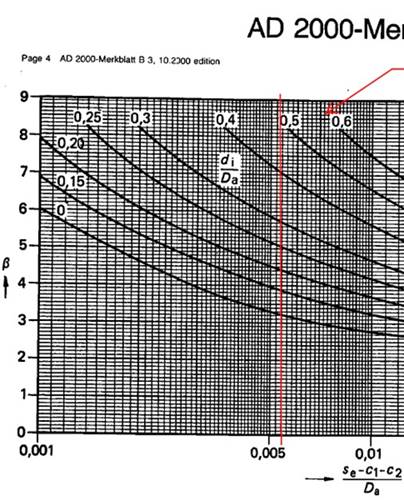
>> it is documented exactly according to AD2000 B3.
DIN V 2505 has been incorporated into the module as an optional reference.
Since it is our endeavor to always deliver the latest versions to our customers, the January 1986 edition has been incorporated. The difference can be found in the preamble to DIN V 25051986 edition.
Quote
"This prestandard contains factually unchanged the contents of the prestandard DIN 2505 , edition 1964. Compared to this prestandard, only the units have been changed from the SI system and the cited standards have been corrected to the latest status."
Answer: The gasket diameter dD and the pitch circle diameter dt of the bolt holes, plus the gasket coefficient k1 and the safety coefficient SD. The calculation coefficient C1 is calculated from these values according to AD -B5 section 6.3.1.
Note: For plates with edge moment, C1 is not specified, unlike plates without edge moment.
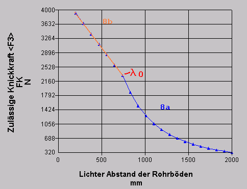
In deviation from B5 6.7.1.5, the permissible buckling force is not only determined according to equation 8a, but in the relevant case that <l l0, according to equation 8b. As the diagram shows, extrapolation of equation 8a into the range of validity of equation 8b would result in permissible buckling forces that are much too high.
A tank is operated with the pressure -1 / 6bar. Must a load change calculationmade from -1 to 6bar?
In this case, it is a load case collective.
First calculate the permissible load cases for the range 0 to 6 bar. Then (if necessary at all) the range 0 to -1 bar.
With the obtained allowable load cycles, form the load spectrumaccording to Meiner's rule (AD 2000 S1 Equation 12).
Example:
Required number of load cycles= 500000
Case 1 (0 - 6bar): results in a permissible load cycle of700000
Case 2 (-1 - 0bar): results in a permissible load cycle of2100000
Thus, according to equation 12:
500000 / 700000 + 500000 / 2100000 = 0,95 <1
The load changes would therefore be permissible.
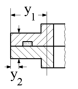
Answer: For metallic O-ring seals, AD B7 Table 1, after Note 5, specifies that bolt forces shall be increased by the ratio of the lever arms y1/y2.
Answer: According to AD B-7 Section 6.1.2.2, the minimum bolt force for the installation condition FDV = pdD k0 kD can be reduced for soft-material and metal soft-material gaskets if F_DV > F_SB (=minimum bolt force for the operating condition). Then, according to Eq. (6): F_DV* = 0.2* F_DV + 0.8* Ö(FSB * FDV). The corresponding formulas can also be found in the results section of table B7.
Note: Since AD -B7 gives a choice in this case, users usually use the reduced bolt forcereduce the flange size. However, there are manufacturers who do not reduce their flanges.
Answer: The bolt force is determined according to module B7
Note: The total bolt force for all bolts must be used. In the AD -B modules, unknown quantities usually refer to previous leaflets with smaller numbers.
Answer: Conical shells are dimensioned according to AD -B2. For taper opening angles phi < 70°, cutouts can be calculated as cylinders according to AD-B9. The equivalent cylinder diameter is according to AD-B2 section 6: Di = (Ds+di*sin(phi))/cos(phi), with Ds = cone diameter in cross section perpendicular to the cone axis at the cutout center, di=cutout diameter axially along the cone wall.
Which values must be entered for the executed wall thickness se and the wall thickness in the cutout area sa?
Answer: se is the wall thickness of the base body outside the cutout without reinforcement; sa is the total wall thickness with reinforcement in the cutout area.
Note: The co-supporting width b is normally not entered and results after entry of the wall thicknesssa.
A calculation with several sections is only valid if a calculation with the largest single section was also performed. The larger value is then decisive for the result. You will receive a corresponding message if you omit the information on the single section in the program and only fill in the multiple sections.
It is correct that the slab thickness can be smaller for multiple cutouts than for a single cutout. In the limit case, imagine a completely perforated slab, for which the slab thickness would then be 0. The balance between loaded and load-bearing cross-section is relevant.
Answer: The regulations mentioned for cutouts in section 5.3 also apply to dished heads. Cutoutscan be located in the calotte or also in the brim due to their function.
If cutouts are in the range of 0.6 * Da, their reinforcement shall be sufficient according to AD ‑Merkblatt B 9 (vA according to Annex 29). In the case of disc-shaped reinforcements, the disc edge must not exceed the range of 0.8 * Da for dished heads and 0.7 * Da for cage arch heads. However, because of the manufacturing effort involved, a disc-shaped reinforcement should be dispensed with wherever possible.
Cutouts in the rim area (i.e. outside 0.6 * Da) should be avoided
if possible. If they are required for functional reasons, the calculation
coefficient must bedetermined btaking into account the
ratio  from Fig.
7 or 8 AD ‑Merkblatt B 3 (Annex 28).
from Fig.
7 or 8 AD ‑Merkblatt B 3 (Annex 28).
If there are several cutouts and the web on the line connecting the centers of adjacent cutouts is not completely within 0.6 * Da , the minimum web width must be equal to the sum of half the cutout diameters.
According to AD ‑Merkblatt B 3 Annex 1, it is recommended to replace the curved bottom with a tapered transition piece for cutout diameters Di > 0.6 Da. This can be ‑dimensioned according to AD leaflet ‑B 4 (see section 7) (tapered shell with brim radius).
Answer: According to AD-M erkblatt W10, a distinction is made between three load cases at low temperatures, which depend on the material and the temperature. Depending on the load case, the safety factors S, or alternatively the calculation pressure, must be multiplied by a coefficient of increase. If the vapor pressure is used as the calculation pressure for volatile substances, the temperature dependence of the vapor pressure must be taken into account.
Example: For material 1.0566 (P355NL1), the following table results according to AD -W10 :
|
1.0566 (P355NL1) |
Case I |
Case II |
Case III |
|
Lowest temperature °C |
- 60 |
- 110 |
- 140 |
|
coefficient |
1 |
4/3 or 2 |
4 |
At a temperature of -100 °C, for example, the safety factor S or the calculation pressure would have to be multiplied by 4/3. If a steel grade of group 1 or 5.1 according to AD-HP 7/2 is used without stress relief heat treatment, the safety factor S must be multiplied by the coefficient 2 for stress case II: 2*S.
Question: When do I need the B9N module?
Answer: For the calculation of nozzles according to AD, we have been providing the modules B9 and B9N for several years. With the B9 module, the verification is carried out to the letter according to the code of practice, and with the B9N module, the verification is logically correct according to AD B9and TRD 301 or 303. There are several technical reasons for using B9N.
In B9N you will also find the calculation of the block flanges.
To block flanges in spherical shells:
First check whether verification is required at all. As a rule, the "largest unreinforced cutout" in spherical shells is considerably larger than the block flange inside diameter.
In the extremely rare case that a verification is required, this can be carried out with a shortened nozzle.
The stresses in the WRC , and WRCK modules are determined according to the Welding Research Council's measurement curves.
Depending on the geometry, between 2 and 3 curves must be interpolated. Unfortunately, the measurement curves do not cover the same range, so that for some curves additional extrapolation is required.
Here it must be decided on a case-by-case basis whether extrapolation is sensible and justifiable. This can be controlled with the options under the "Extra" menu
Question: Different voltages occurat Probad = 137.96 and at WRC = 191.1.
In your calculation with Probad, a transition radius of 3 mm was entered, but the notch factors Kn and Kb are set to 1. This is only permissible if the nozzle loads are static. If alternating loads occur, the stress increases due to the notch effect must be taken into account.
In our program, this is regulated in such a way that a transition radius > 0 mm automatically takes the notch factors into account, and thus also the loading by dynamic loads.
As an attachment, you will receive a calculation without taking the notch factors into account. As you can see, the results agree.
By the way, we took over the source code for our WRC program from TÜV Baden in 1986. The program has been in use ever since. From time to time there are discussion points about how to handle the "shortcomings" of the WRC Bulletin, especially how to handle a possible extrapolation. In the menu item "EXTRA" we provide several options for this.
Example: Visual Basic 6.0
1. Create a new Standard Exe project
2. Place a command button on the shape
3. In the code area please enter the following lines
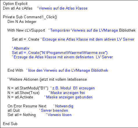
4. Start your project.
How can these forces bejustified?
According to ASME UG36 c, 3 ½ '' or 2 3/8 '' nozzles do not have to be verified depending on the given boundary condition. In these cases, the shell area reserve is greater than the area loss due to the opening. This results in the negative values.