Damage prevention at tube vibration
· Decreasing the support length
· Increasing the tube diameter
· Increasing the tube wall thickness
· Increasing the spacing ration at staggered tube arrangement (60° or 45°)
·
The bore in the baffle should be as small as
possible.
Recommended: Gap between tube and baffle ≤ 0.3 mm and
chamfering the bores
A high degree of danger results from:
· the velocity peak under the nozzles and at the radial trailing edge of an impingement plate.
· the inclined flow of the tubes in the first tube row at staggered tube arrangement and spacing ratios > 1.3
· vortex shedding
Counter-measures:
· Increase nozzle size
· Move nozzle near baffle
· Installation of a supporting plate in the nozzle center
· Remove most upper tube row(s)
· No tubes in window
·
Use impingement protection
Please note: This might increase the risk of vibration excitation, if
there are higher flow velocities due to the arrangement of the impingement
plate. (s. Impingement protection)
As a rule, the first or second tube row in the window zone are the most endangered tube rows.
Counter-measures:
· Installation of supporting grids or partial supporting grids
· No-tubes-in-window
· Distance of baffle edge to first window row > 0.1 · da
· If the baffle edge lies within the center of a tube row, the semi-circle bore diameter should be > 1,2 · da .
· Tie rods outside the tube bundle might be endangered by vortex shedding or turbulence excitation.
Impingement plates protect the tubes against cavitation and erosion. Normally they increase the risk of vibration excitation due to a great local velocity at the radial trailing edge of an impingement plate, which does not cover all rows of the first tube row..
Constructive counter-measures:
· Circular impingement plates should have a diameter of > 1.2 · dnozzle and holes like a perforated plate.
· Remove endangered rows in the first tube row and check the rest risk of the outer tubes in the second tube row.
· Impingement plates with rectangular shape should be brought close to the shell wall.
· Installation of a partial supporting plate in the nozzle center for the first tube rows.
·
A louvre distributor is quite suitable for impingement
prevention as well as for flow distribution
(s. VDI-Waermeatlas, 11. edition, Module O1, Hints on the Construction of Heat
Exchangers, Fig 21 - b)
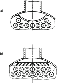
Fig 21 – Designs of impingement protection: a) plate b) louver
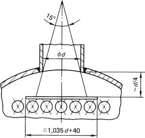
Fig. 22 - Arrangement of impingement plates.
VDI-Waermeatlas 11th edition, chapter O2, section 5.6, Constructive design