HPR-e
|
Description |
Sketch |
Shape factor H |
Flexibility |
Stres intensification factor |
Section |
|
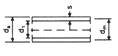
Straight pipe |
|
1 |
1 |
1 |
|
|
Straight pipe elbow 1) |
|
|
|
|
|
|
Segment bend 1) with
|
|
with
|
|
|
|
|
Segment bend 1) 2) with
|
|
with
|
|
|
|
|
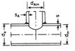
T-piece 3) with weld-on, weld-in or necked-on nozzle |
|
|
1 |
|
Base pipe:
Nozzle:
with
sx as minimum and sx2 = i·sA |
|
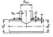
3) as above, but with additional reinforcement ring |
|
|
1 |
|
|
|
3) Pressed weld-in T-piece with s and sA as connection wall thicknesses |
|
|
1 |
|
|
|
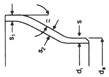
Pressed weld-in reducer |
|
Shape conditions s ≥ da/100 s2 ≥ s1 |
1 |
max. 2,0 (α in grd) |
|







1) For pipe bends which are stiffened by a flange or similar at a distance smaller than dm/2 from the beginning or end of the bend, kB and i must be replaced by
k'B = c·kB
i' = c·i
The following applies:
c = h1/6 with one-sided stiffening
c = h1/3 with stiffening on both sides
2) These bends are divided into individual bends with radius r and straight spacers of length l1 = 1-2 - r - tan α . The values for r, kB and i therefore also apply to individual segment seams.
3) In the case of T-pieces, the base pipe and nozzle are examined separately. For the base pipe, the decisive moment is the larger of the two resulting moments to the left and right of the axis intersection point. For the connecting piece, the resulting moment from the branching line applies. To simplify matters, it can be referred to the intersection point of the axis or, more precisely, to the point a
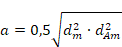
at a distance from the intersection point of the axis.