VDI Heat Atlas eReference
Dr. S. Gusev
In chapter M2 of the VDI Heat Atlas there is a calculation model of the heat transfer from the heat carrier fluid through the wall construction. This model is based on the solution .for the heat flux through heat transfer in rectangular bodies. The heat transfer coefficient is calculated as follows:
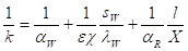 (Eq.1)
With:
|
l |
= |
Distance between coils |
|
X |
= |
Mean radius of half pipe |
|
Sw |
= |
Wall thickness |
|
lw |
= |
Thermal conductivity of the wall |
|
aw and aR |
= |
Heat transfer coefficients of outer and inner surface |
If X=l there is one dimensional thermal conduction and the correction factors e and c are exactly one.
If X/l < 1 there is a two-dimensional thermal conduction and e and c are less than 1. In the VDI Heat Atlas there are some polynomial functions for determining these correction factors. These functions are valid as follows:
c:  ,
, 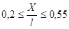 ,
, 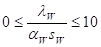 (Eq.
2)
(Eq.
2)
e:  ,
,  (Eq.
3)
(Eq.
3)
When using these polynomial functions, values for c can be negative.
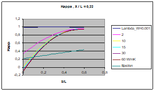
Figure 1a
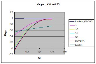
Figure 1b
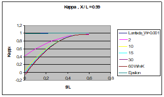
Figure 1c
Figures 1a to c: Correction factors e and c
In figures 1a - c you can see that for small s/l c<0 ! This is strange especially in the case X/l=0,99. If ec»1 should be valid (Figure 1c).
Tod avoid this unreasonable situation, we suggest the following. There should be a limitation of the product ec.
For very thin walls, if  , the method does only become
one dimensional in the area x.
, the method does only become
one dimensional in the area x.
We calculate the heat transfer coefficient of the inner surface.
We get asymptotically  .
.
We suggest the following equation:
 (Eq.
4)
(Eq.
4)
The results are represented in figures 2a and 2b.
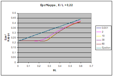
Figure 2a
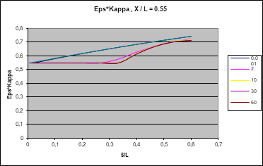
Figure 2b
Figures 2a and 2b: Corrected correction factors e and c
In example 1 of the VDI Heat Atlas chapter M2, k is calculated as k = 208 W/(m² K). In this case there is also
 <
<  .
.
By means of using the corrected correction factors e and c we get k = 215 W/(m² K).
The accuracy of equations (1) and (4) can only be determined by a comparison of numerical results.
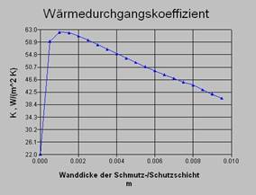
Using the fictitious wall thickness leads to unreasonable results: An increase of the additional layer thickness increases the heat transfer coefficient! See Figure 3.
|
|
This is a result of a change in geometry of the body when using a fictitious wall thickness. Due to the additional layer, we must increase the value of sw. This leads to an increase of the values of the correction factors e and c , and we get an additional increase of the heat transfer coefficient k. The simplest way to avoid this problem is: We do not use a fictitious wall thickness. |
According to the one dimensional theory, we add a new term in equation (4) which is connected with the thermal resistance of the additional layer. For the calculations we get a new equation:
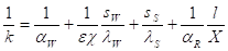 (Eq.
5)
(Eq.
5)
In equation (5) we calculate correction factors e and c by using the wall thickness Sw. They are independent from the additional layer thickness Ss and the heat trransfer coefficient is getting smaller when increasing Ss.
The application of the new equation is shown in Figure 4. To compare example 1 of the VDI Heat Atlas, there are shown two dependencies for the heat transfer coefficient k in figure 4. The first dependency is according to VDI Heat Atlas chapter M2 equation 1 (with fictitious wall thickness) and the second according to equation (5).
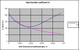
Figure 4. Heat transfer coefficient K
In the area Ss ≤ 3 mm the equations bring the same results.
In the area Ss > 3 mm equation (5) leads to more realistic results.
Literature
1. VDI Heat Atlas
2. Heidemann, W.: Zur rechnerischen Ermittlung instationärer Temperaturfelder in geschlossener und diskreter Form. Diss. University Stuttgart 1995.
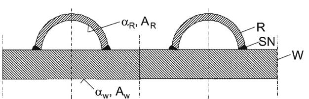
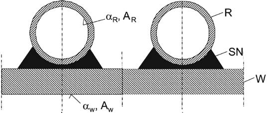
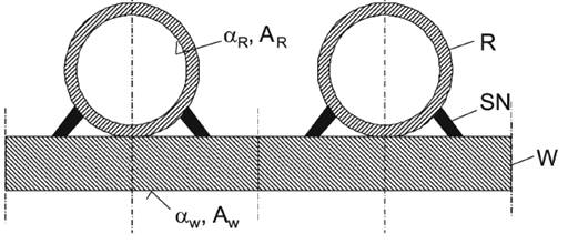
R=tube SN=welded seam W=wall
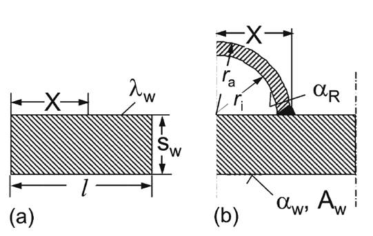
Cross section of welded on half pipe. (a) Part of the vessel wall, (b) symmetrical part.
R=tube SN=welded seam W=wall
Cross section of welded on full pipe with intermediate layer. (a) Simplified parts, (b) Symmetrical geometry
R=tube SN=welded seam W=wall
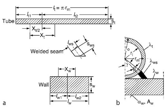
Cross section of welded on full pipe. (a) Simplified parts, (b) Symmetrical geometry
R=tube SN=welded seam W=wall
Cross section of welded on half pipe. (a) Part of the vessel wall, (b) symmetrical part.
Welded on full pipe
Welded on full pipe with intermediate layer