AD 2000 S1
|
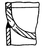
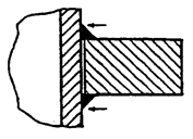
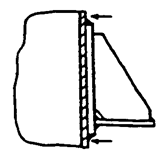
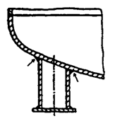
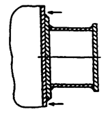
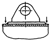
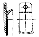
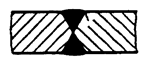
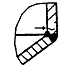
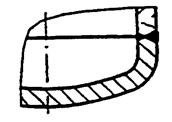
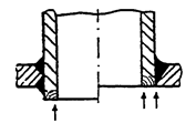
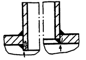
Table 3. Examples of construction types and welded connections with the corresponding classes (K 0, K 1, K 2, K 3) and the corresponding stress factor h (depicted rupture paths exemplary) |
|||||
|
No. |
Figure |
Description |
Provision |
Class |
h |
|
1. Cylindrical and conical shells, dished ends |
|||||
|
1.1 |
|
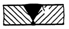
Longitudinal or circumferential weld with equal wall thicknesses |
Welded on both sides |
K 1 |
3,01) |
|
1.2 |
|
|
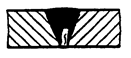
Welded on one side with counter weld |
K 1 |
|
|
1.3 |
|
|
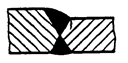
Welded on one side without counter weld |
K 2 |
|
|
1.4 |
|
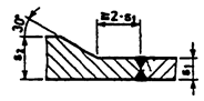
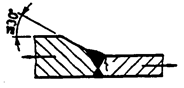
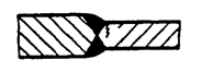
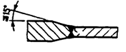
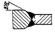
Longitudinal or circumferential weld with unequal wall thicknesses |
Welded on both sides |
K 1 |
1,52) |
|
1.5 |
|
|
|
K 1 |
|
|
1.6 |
|
|
|
K 1 |
|
|
1.7 |
|
|
Welded on both sides, Same offset of edges inside and outside |
K 1 |
|
|
1.8 |
|
|
|
K 1 |
|
|
1.9 |
|
|
|
K 1 |
|
|
1.10
|
|
Cone with corner joint |
Welded on both sides or welded on one side with counter weld |
K 1 |
2,7 |
|
1.11
|
|
Welded on one side without counter weld |
K 3 |
|
|
|
1.12 |
Cone with knuckle and longitudinal weld |
Seam and class assignment as No 1.1-1.3 |
K 1 / K2 |
2,0 |
|
|
1.13 |
|
Head to shell joint for dished ends with cylindrical skirt heights acc. to AD-Merkblatt B 3 |
Seam and class assignment as No 1. 1 -1.9 |
K 1 |
1,5 |
|
1.14
|
Knuckle of Klöpper type |
Not welded |
K 0 |
2,5 |
|
|
1.15 |
Knuckle of Korbbogen type |
Not welded |
K 0 |
2,0 |
|
|
Table 3. Examples of construction types and welded connections wit the corresponding classes (K 0, K 1, K 2, K 3) and the corresponding stress factor h (depicted rupture paths exemplary) |
|||||
|
No. |
Figure |
Description |
Provision |
Class |
h |
2. Nozzle welds |
|||||
|
2.1 |
|
Set-through or set-in nozzle |
Welded on both sides or welded on one side with counter weld |
K 1 |
3,0 |
|
2.2 |
|
Welded on one side without counter weld |
K 2 |
|
|
|
2.3
|
|
Set-through nozzle (left type in the figure) |
Welded on both sides but not continuously welded |
K 2 |
|
|
2.4
|
Set-in nozzle (right type in the figure) |
|
K 3 |
|
|
|
2.5 |
|
Set-on nozzle |
Welded on one side (no remaining gap), Nozzle drilled or weld root polished |
K 1 |
|
|
2.6 |
|
|
Welded on one side without counter weld or without mechanical processing of the root. |
K 2 |
|
|
2.7
|
|
Nozzle with disk type reinforcement. Seam: at outside diameter of the disk |
|
K 3 |
|
|
2.8 |
Nozzle with disk type reinforcement. Seam: Nozzle weld |
Joint of nozzle pipe with shell and reinforcement disk welded |
K 1 |
|
|
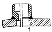
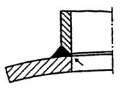
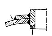
|
Table 3. Examples of construction types and welded connections wit the corresponding classes (K 0, K 1, K 2, K 3) and the corresponding stress factor h (depicted rupture paths exemplary) |
|||||
|
No. |
Figure |
Description |
Provision |
Class |
h |
|
3. Flanges, block flanges and bolts |
|||||
|
3.1 |
|
Welding neck flange |
Welded on both sides or welded on one side with counter weld |
K 1 |
2,0 |
|
3.2
|
|
Welded on one side without counter weld |
K 2 |
|
|
|
3.3 |
|
Slip-on weld flange |
Weld according to AD-Merkblatt B 8, Table 1 |
K 2 |
3,0 |
|
3.4 |
|
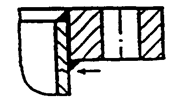
Set-in block flange |
Welded on both sides or welded on one side with counter weld |
K 1 |
|
|
3.5 |
|
|
Welded on both sides but not continuously welded |
K 2 |
|
|
3.6 |
|
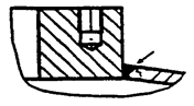
Set-in block flange with welding hub |
Welded on both sides or welded on one side with counter weld |
Kl |
|
|
3.7 |
|
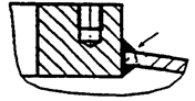
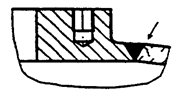
Set-on block flange. Weld at inside diameter (left weld in the figure) |
|
K 3 |
4,0 |
|
Set-on block flange. Weld at outside diameter (right weld in the figure) |
|
K 2 |
|
||
|
3.8 |
|
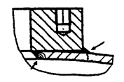
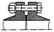
Bolts of flanged connections:
As a rule a proof is only required, if the bolts are loosened frequently. In this cases the values in brackets K 0 und h = 5,0 are valid |
(K 0) |
(5,0) |
|
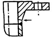
|
Table 3. Examples of construction types and welded connections wit the corresponding classes (K 0, K 1, K 2, K 3) and the corresponding stress factor h (depicted rupture paths exemplary) |
|||||
|
No. |
Figure |
Description |
Provision |
Class |
h |
4. Bolted, attached or clamped flat plates with openings Range of validity and supplementary notes: - Stress factors h are valid for ends with central openings if the following conditions for the opening are fulfilled: (Terms s. AD-Merkblatt B 5 and B 9): di / D1 £ 0,2 and ss / s ³ 1,25 × di / D1 + 0,1 for reinforced openings and di / D1 £ 0,2 for unreinforced openings - reinforced openings weld and class assignment as numbers 2.1-2.6, 3.3-3.7 - unreinforced openings (flat plates without weld): Class K 0 |
|||||
|
4.1
|
|
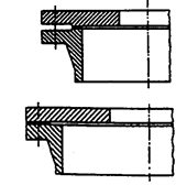
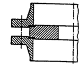
Bolted plates with and without peripheral momenmt |
s. " Range of validity and supplementary notes " for No. 4
|
K0-K3 |
3,0 |
|
4.2
|
|
Plate attached from the internal or external side |
|||
|
4.3 |
|
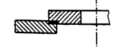
Simply supported flat plate
|
|||
|
Table 3. Examples of construction types and welded connections wit the corresponding classes (K 0, K 1, K 2, K 3) and the corresponding stress factor h (depicted rupture paths exemplary) |
||||||
|
No. |
Figure |
Description |
Provision |
Class |
h |
|
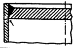
5. Joint weld of flat ends Range of validity and supplementary notes: Classes K and stress factors h are also valid for ends with central openings if the following conditions for the opening are fulfilled: (Terms s. AD-Merkblatt B 5 and B 9):: di / D1 £ 0,2 and ss / s ³ 1,25 × di / D1 + 0,1 for reinforced openings and di / D1 £ 0,2 for unreinforced openings |
||||||
|
5.1 |
|
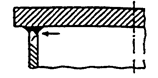
Welded end |
Welded on both sides |
K1 |
5,0 |
|
|
5.2 |
|
|
Welded on both sides but not continuously welded |
K2 |
|
|
|
5.3 |
|
|
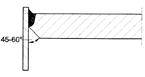
Welded on one side without counter weld |
K3 |
||
|
5.4 |
|
Welded end with relief groove |
Welded on one side, Groove dimensions acc. to AD-Merkblatt B 5, Table 1, Type 6 |
K2 |
4,0 |
|
|
5.5 |
|
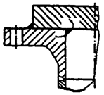
End welded to a welding neck flange or slip-on flange |
Welded on both sides with fillet welds |
K2 |
5,0 |
|
|
5.6
|
|
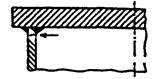
Welded end |
Welded on both sides or welded on one side with counter weld
|
K1 |
|
|
|
5.7 |
|
|
Welded on both sides but not continuously welded |
K2 |
|
|
|
5.8 |
|
|
Welded on one side |
K3 |
|
|
|
5.9 |
|
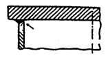
Partially welded end |
Welded on one side |
K3 |
5,0 |
|
|
5.10
|
|
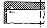
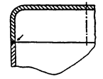
End with knuckle Joint weld |
Knuckle radius and skirt height acc. AD-Merkblatt B 5,Table 1, type a, Weld and class assignment as number 1.1-1.3 |
Kl/K2 |
1,5 |
|
|
5.11 |
End with knuckle, Knuckle |
Not welded |
K0 |
2,0 |
||
|
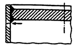
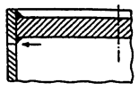
5.12 |
|
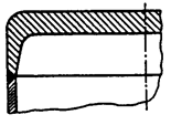
Forged or pressed end |
Knuckle radius and skirt height acc. AD-Merkblatt B 5,Table 1, type b, Weld and class assignment as number 1.1-1.3 |
K1/K2 |
1,5 |
|
|
5.13 |
Forged or pressed end, Knuckle |
Not welded |
K0 |
4,0 |
||
|
Table 3. Examples of construction types and welded connections wit the corresponding classes (K 0, K 1, K 2, K 3) and the corresponding stress factor h (depicted rupture paths exemplary) |
|||||
|
No. |
Figure |
Description |
Provision |
Class |
h |
6. Jacket – Joint welds |
|||||
|
6.1 |
|
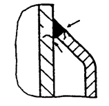
With integrated knuckle:
The evaluation is valid for the inner vessel and for the joint weld |
Welded on one side |
K 2 |
3,0 |
|
6.2 |
|
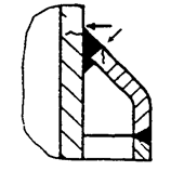
With separate knuckle: The evaluation is valid for the inner vessel wall and for the joint weld of knuckle and inner vessel wall. ( The joint weld of knuckle and outer vessel wall is classified as number 1.3 with K 2) |
Welded on both sides or welded on one side with counter weld |
K 1 |
3,0 |
|
Table 3. Examples of construction types and welded connections wit the corresponding classes (K 0, K 1, K 2, K 3) and the corresponding stress factor h (depicted rupture paths exemplary) |
||||||
|
No. |
Figure |
Description |
Provision |
Class |
h |
|
|
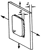
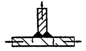
7. Welded attachments, general Provision: External appearance of the welds acc. EN 25817, classification group B, excluding the characteristics weld reinforcement, lower deviation of the weld and being non-isosceles |
||||||
|
7.1
|
|
Welded attachments without transmitting changing tensile forces and moments
7 The evaluation refers to rib center. For the rib end, the classification is one class worse each. |
Welded on both sides |
K1 |
2,0
|
|
|
7.2 |
Welded on both sides with filet weld |
K2 |
||||
|
7.3
|
|
Welded on both sides |
K17 |
|||
|
7.4 |
Welded on both sides with filet weld |
K27 |
||||
|
7.5 |
|
Reinforcement plate, filler plate with fillet weld joint. No transmitting of changing tensile forces and moments |
s2 £ 1,5 · s1
r ³ 2 · s2 |
K2 |
||
|
7.6
|
|
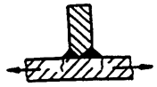
Welded attachments with transmitting changing tensile forces and moments |
Welded on both sides |
K1 |
3,0 |
|
|
7.7 |
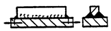
Welded on both sides but not continuously welded |
K2 |
||||
|
Table 3. Examples of construction types and welded connections wit the corresponding classes (K 0, K 1, K 2, K 3) and the corresponding stress factor h (depicted rupture paths exemplary) |
|||||
|
No. |
Figure |
Description |
Provision |
Class |
h |
|
8. Welded attachments without transmitting of changing tensile forces or moments, examples Provision: External appearance of the welds acc. EN 25817, classification group B, excluding the characteristics weld reinforcement, lower deviation of the weld and being non-isosceles |
|||||
|
8.1 |
|
Vessel with skirt support |
Welded on one side |
K2 |
2,0 |
|
8.2 |
|
Vessel wall with ring support |
Welded on both sides but not continuously welded |
K2 |
2,0 |
|
8.3 |
Vessel wall with ring stiffener |
K2 |
|
||
|
8.4 |
Welded in circumferential direction but not continously welded |
K3 |
|
||
|
8.5 |
|
Vessel wall with support bracket (with or without reinforcement) |
Welded on one side |
K2 |
|
|
8.6 |
|
Vessel wall with leg support (with or without reinforcement) |
Welded on one side |
K2 |
|
|
8.7 |
|
Vessel wall with trunnion (with or without reinforcement) |
Welded on one side |
K2 |
|
|
8.8 |
|
Vessel wall with lifting lug (with or without reinforcement) |
Welded on one side |
K2
|
|
|
8.9 |
|
Vessel wall with lifting lug (with or without reinforcement) |
Welded on one side |
K2 |
|