Additional information for EN 09 module
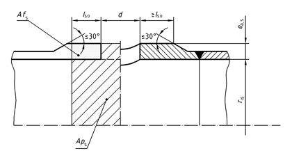
Figure 9.4-1 — Cylindrical shell with isolated opening and increased wall thickness
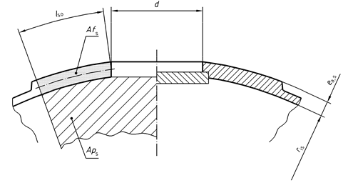
Figure 9.4-2 — Spherical shell or dished end with isolated opening and increased wall thickness
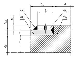
Figure 9.4-3 — Cylindrical shell with isolated opening and reinforcing plate
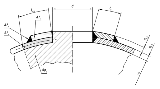
Figure 9.4-4 —Spherical shell or dished end with isolated opening and reinforcing plate
Figure 9.4-5 — Cylindrical shell with isolated opening and reinforcing ring, with external blind flange B
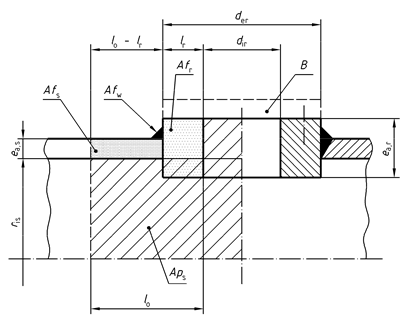
Figure 9.4-5 — Cylindrical shell with isolated opening and reinforcing ring, with external blind flange B
Figure 9.4.6— Spherical shell or dished end with isolated opening and reinforcing ring, with internal blind flange B
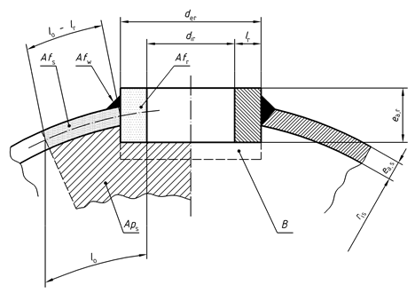
Figure 9.4.6— Spherical shell or dished end with isolated opening and reinforcing ring, with internal blind flange B
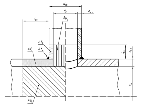
Figure 9.4-7 — Cylindrical shell with isolated opening and set-on nozzle
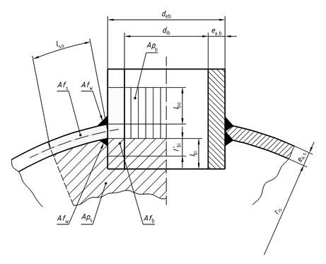
Figure 9.4-8 — Spherical shell or dished end with isolated opening and set-in nozzle
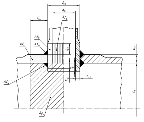
Figure 9.4-9 — Spherical shell or dished end with isolated opening and set-in nozzle
Figure 9.4-10 — Spherical shell or dished end with isolated opening and shell, nozzle and reinforcing plate
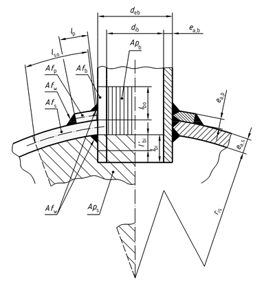
NOTE The various lengths and areas shown for the case of a nozzle with a reinforcing plate in a sphere also applies to the case of a nozzle with a reinforcing plate in a cylinder.
Figure 9.4-10 — Spherical shell or dished end with isolated opening and shell, nozzle and reinforcing plate
Figure 9.4-11 — Cylindrical shell with isolated opening and a butt-weld nozzle (see X) or an extruded shell (see Y)
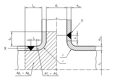
Figure 9.4-11 — Cylindrical shell with isolated opening and a butt-weld nozzle (see X) or an extruded shell (see Y)
Figure 9.4-12 — Spherical shell or dished end with isolated opening extruded from the shell, with internal blind flange B
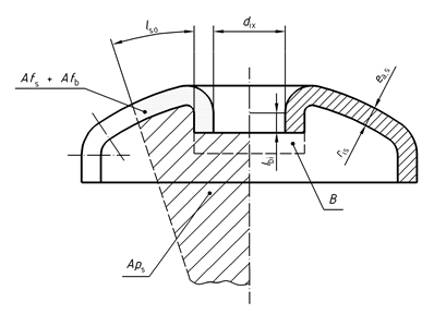
Figure 9.4-12 — Spherical shell or dished end with isolated opening extruded from the shell, with internal blind flange B
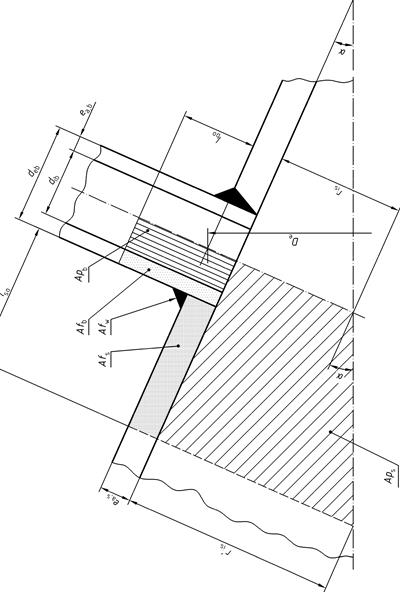
Figure 9.4-13 — Conical shell with isolated opening. Combined reinforcement from shell and nozzle
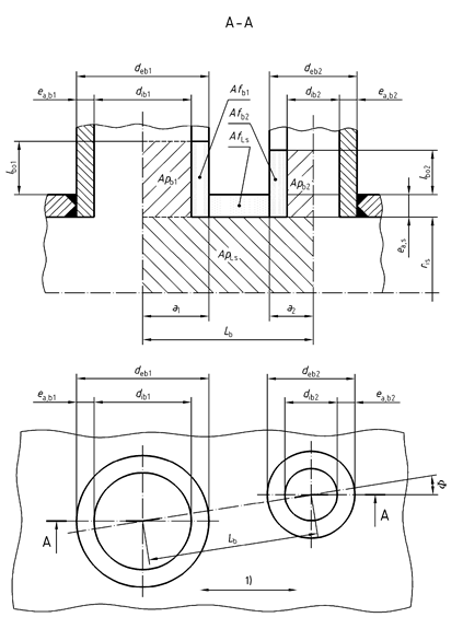
Key
1) direction of the generatrix
NOTE The cross section shown in this figure illustrate the case when Φ = 0
Figure 9.6-1 — Ligament check of adjacent nozzles normal to a cylindrical shell
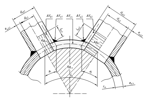
Figure 9.6-3 — Ligament check of adjacent nozzles normal to a spherical shell
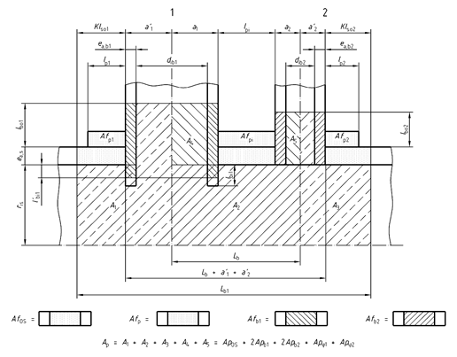
Figure 9.6-5 — Overall check of adjacent nozzles in a cylindrical shell
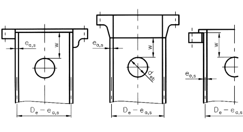
Figure 9.7-5 — Opening in a cylindrical shell, close to the junction with a flange
Figure 9.7-6 — Opening in a cylindrical shell, close to the junction with the smaller diameter of a conical reducer
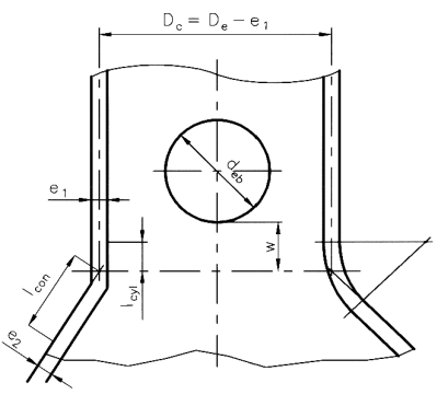
Figure 9.7-6 — Opening in a cylindrical shell, close to the junction with the smaller diameter of a conical reducer
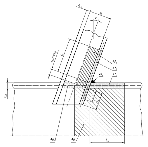
Figure 9.5-1 – Cylindrical shell with nozzle oblique in the longitudinal cross section
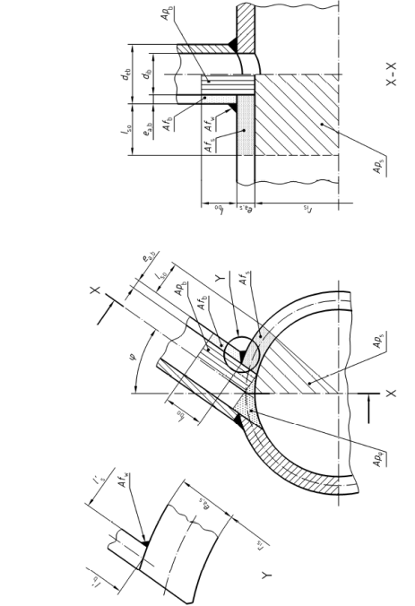
Figure 9.5-2– Cylindrical shell with nozzle oblique in the transverse cross section
9.4.6 Effective thickness for nozzles
9.4.6.1 in fatigue applications where fatigue is assessed using Clause 17 and if the opening is a critical area (as defined in 17.2)
The ratio eb/ea,s shall not exceed the value taken from the graph in Figure 9.4-14 and the value of eb shall never exceed the value of ea,b. Nozzle thickness in excess of that calculated using Figure 9.4-14 shall not be included in the reinforcement calculation.
Furthermore the ratio ea,b/ea,s shall not exceed the value taken from the graph in Figure 9.4-15.
NOTE 1 eb is the effective thickness of the nozzle, to be used for the verification of the reinforcement; ea,b is the analysis thickness of this nozzle; the ratio eb/ea,s limits the contribution of the nozzle to the resistance of the opening; the ratio ea,b/ea,s limits the analysis thickness of the nozzle, and thus its manufacturing thickness, in order to limit the stresses which can occur due to great thickness differences and to avoid the fatigue problems which can result.
NOTE 2 When fatigue is assessed using Clause 18, no limitation to the thickness ratio is necessary because in that case more accurate stresses are used for fatigue calculations.
9.4.6.2 in creep applications (i.e.: when the calculation temperature is situated in the creep range)
The effective thickness eb may be taken equal to the analysis thickness ea,b of the nozzle.
However the ratio ea,b/ea,s shall not exceed the value taken from the graph in Figure 9.4-15.
9.4.6.3 in applications without creep and without fatigue assessment using Clause 17 (i.e.: when the calculation temperature is situated out of the creep range and the opening is not a critical area as defined in 17.2)
The effective thickness eb may be taken equal to the analysis thickness ea,b of the nozzle and no limitations apply to the ratio ea,b/ea,s .
9.5.2.3.2.2 Nozzle with a longitudinal weld
If a nozzle has a longitudinal weld having a weld joint factor z, the value fb for the nozzle material shall be replaced by fb·z except for openings in cylindrical or conical shells if the angle θ as defined in Subclause 9.3.2 is greater than 45°.