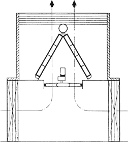
OB-e
eReference Springer Verlag
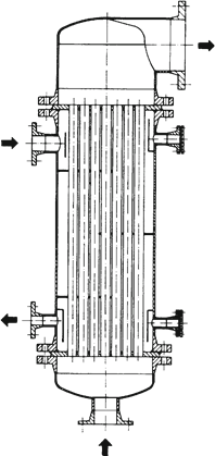
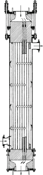
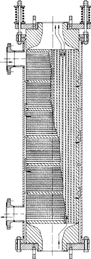
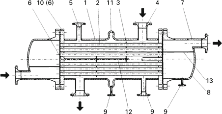
Fig. 1 - Parts of a shell-and-tube heat exchanger with two tube sheets and an expansion joint in the shell
|
1
|
Shell
|
8
|
Dished head
|
|
2
|
Inner tube
|
9
|
Drain connection
|
|
3
|
Segmental baffle; support plate
|
10
|
Stationary head flange
|
|
4
|
Shell nozzle
|
11
|
Expansion joint
|
|
5
|
Vent connection
|
12
|
Tie rods
|
|
6
|
Tube sheet
|
13
|
Pass partition
|
|
7
|
Dished head nozzle,
|
|
|
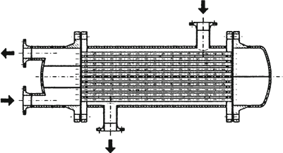
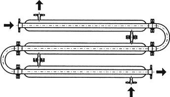
Fig. 2 – Four-pass shell-and-tube heat exchanger with two fixed tube sheets
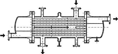
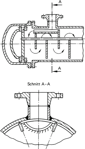
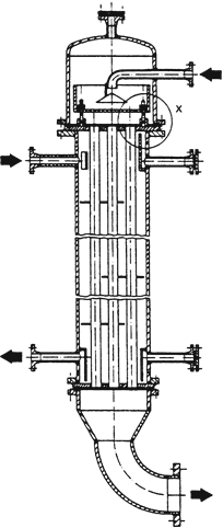
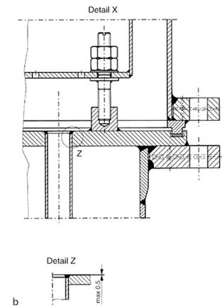
Fig. 3 - Shell-and-tube heat exchanger with expansion joint
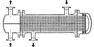
Fig. 4 - Shell-and-tube heat exchanger with floating head
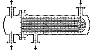
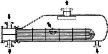
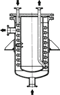
Fig. 5 - Shell-and-tube heat exchanger with U-tubes
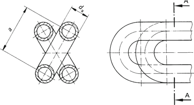
Fig. 6 - Arrangement of U-tubes
Fig. 7 – Shell-and-tube heat exchanger, kettle-type reboiler
Fig. 8 – Typical pass layouts in multiple-pass heat exchangers
|
Entrance head
|

|

|

|

|
|
Return head
|

|

|

|

|
|
Number of passes
|
1
|
2
|
4
|
8
|
Fig. 9- Square and triangular tube pitch patterns
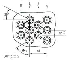
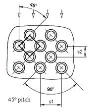
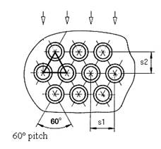
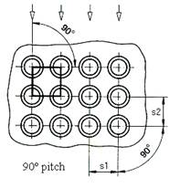
Square and triangular tube pitch
patterns. The inflow angle is shown in each case.
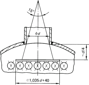
Fig. 10 – Estimation of outer tube limit (OTL)
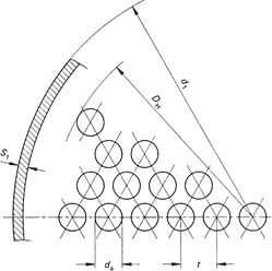
Estimation of outer tube limit (OTL)
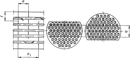
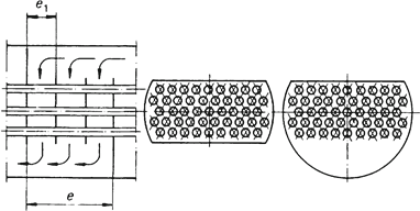
Fig. 11 - Segmental baffle in heat exchanger completely filled with tubes
Fig. 12 - Segmental baffle in heat exchanger partly filled with tubes
Fig. 13 – Segmental baffle with sheet-metal deflector
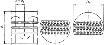
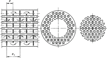
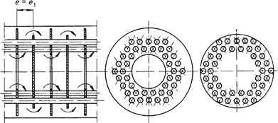
Fig. 14 - Disc and doughnut baffles in heat exchanger completely filled with tubes
Fig. 15 - Disc and doughnut baffles in heat exchangers with no tubes in window
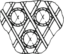
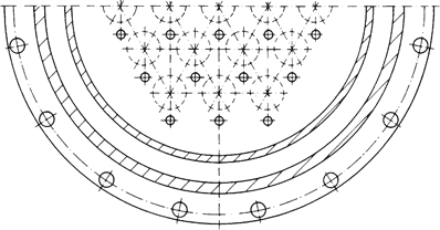
Fig. 16 – Tube pitch plan
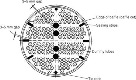
Tube pitch plan with dummy tubes, sealing
strips, spacers, and segmental baffles
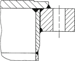
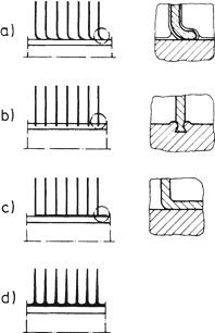
Fig. 17 - Means of securing tubes in the tube sheet
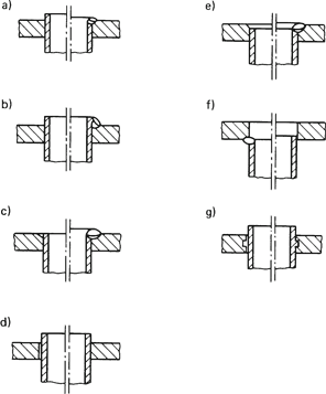
Means of securing tubes in the tube sheet
(17a to 17d acc. to EN 1708-1)
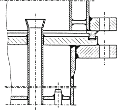
Fig. 18 – Thin tube sheet
Fig. 19 – Thick tube sheet
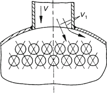
Fig. 20 - Flow velocities v1 and v2 at shell-side inlet and between the tubes
Fig. 21 – Designs of impingement protection
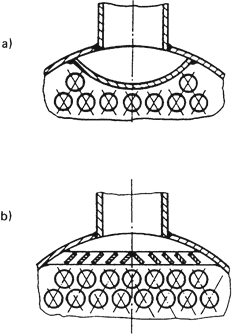
Designs of impingement protection: a) plate b) louver.
Fig. 22 - Arrangement of impingement plates
Fig. 23 – Supporting grid
Fig. 24 - Baffle to reduce dead space
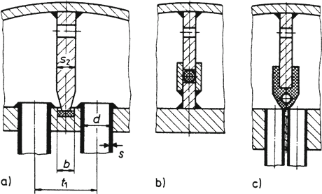
Fig. 25 - Seals for pass partition plates in dished head
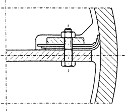
Fig. 26 - Seal on longitudinal partition plate
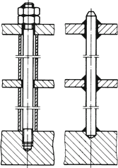
Fig. 27 - Tie rods for segmental or support baffles
Fig. 28 - Thermosyphon Reboiler
Fig. 29 – Robert evaporator
Fig. 30 – Falling-film evaporator
Fig. 31 - Perforated-plate distributor
Fig. 32 - Tulip-shaped evaporator tube inlet
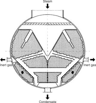
Fig. 33 - Pattern of tubes in a vacuum condenser
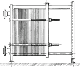
Fig. 34 - Assembled plate heat exchanger
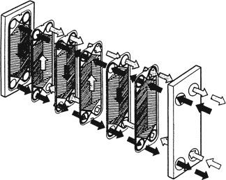
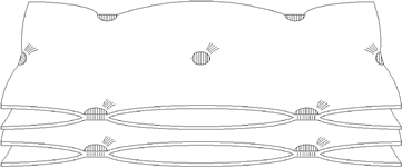
Fig. 35 - Flow pattern in plate heat exchanger
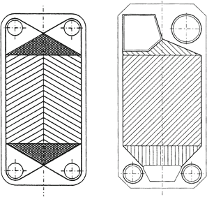
Fig. 36 - Individual plates for (a) heater and (b) evaporator
Fig. 37 - Profile of welded plates
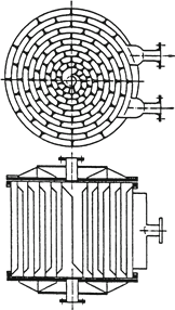
Fig. 38 – Spiral heat exchanger
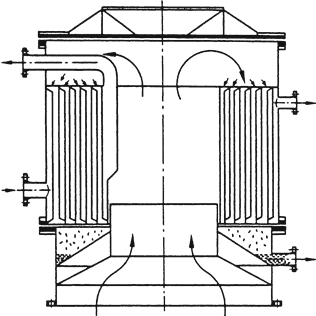
Fig. 39 - Spiral-plate heat exchanger used as condenser
Fig. 40 - Helical-tube heat exchanger
Fig. 41 - Double-tube heat exchanger
Fig. 42 - Safety heat exchanger
Fig. 43 - Graphite shell-and-tube heat exchanger
Fig. 44 - Graphite block heat exchanger
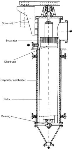
Fig. 45 - Thin-film heat exchanger
Fig. 46 - Rotors in thin-film heat exchanger
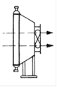
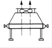
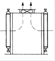
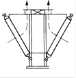
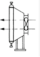
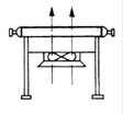
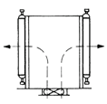
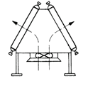
Fig. 47 - Air-cooled heat exchangers
|
|
Vertical
|
Horizontal
|
Rows
|
V-roof
|
|
Suction
|
|
|
|
|
|
|
A-roof
|
|
Pressure
|
|
|
|
|
Fig. 48 - Circular and oval finned tubes
Fig. 49 - Various types of fins
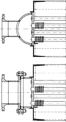
Fig. 50 - Designs for dished ends on air-cooled heat exchangers
Fig. 51 - Air-cooled heat exchanger with silencer