S1-e
1.9
For low allowable temperatures within the application limits of load cases II and III according to AD 2000-Merkblatt W 10, reducing the number of load cycles is not required.
7.3.6
For low allowable temperatures below -200°C you have to shorten the checking intervals by half, i.e. the internal checks per section 7.3.1 and 7.3.4 have to be performed after having reached one quarter of the determined number of load cycles at the latest.
|
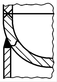
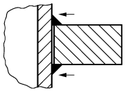
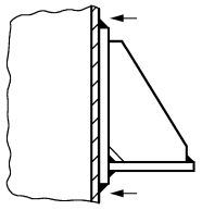
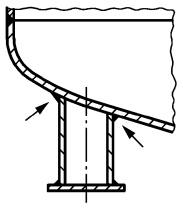
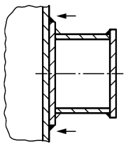
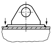
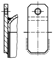
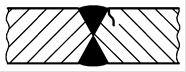
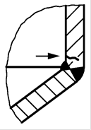
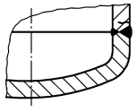
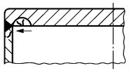
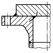
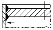
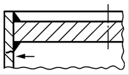
Table 3. Examples of construction types and welded connections with the corresponding classes (K 0, K 1, K 2, K 3) and the corresponding stress factor h (depicted rupture paths exemplary) |
|||||
|
No. |
Figure |
Description |
Provision |
Class |
h |
|
1. Cylindrical and conical shells, dished ends |
|||||
|
1.1 |
|
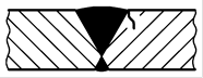
Longitudinal or circumferential weld with equal wall thicknesses |
Welded on both sides |
K 1 |
3,01) |
|
1.2 |
|
|
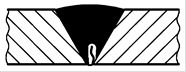
Welded on one side with counter weld |
K 1 |
|
|
1.3 |
|
|
Welded on one side without counter weld |
K 2 |
|
|
1.4 |
|
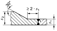
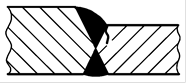
Longitudinal or circumferential weld with unequal wall thicknesses |
Welded on both sides |
K 1 |
1,52) |
|
1.5 |
|
|
|
K 1 |
|
|
1.6 |
|
|
|
K 1 |
|
|
1.7 |
|
|
Welded on both sides, Same offset of edges inside and outside |
K 1 |
|
|
1.8 |
|
|
|
K 1 |
|
|
1.9 |
|
|
|
K 1 |
|
|
1.10
|
|
Cone with corner joint |
Welded on both sides or welded on one side with counter weld |
K 1 |
2,7 |
|
1.11
|
|
Welded on one side without counter weld |
K 3 |
|
|
|
1.12 |
Cone with knuckle and longitudinal weld |
Seam and class assignment as No 1.1-1.3 |
K 1 / K 2 |
2,0 |
|
|
1.13 |
|
Head to shell joint for dished ends with cylindrical skirt heights acc. to AD-Merkblatt B 3 |
Seam and class assignment as No 1. 1 -1.9 |
K 1 |
1,5 |
|
1.14
|
Knuckle of Klöpper type |
Not welded |
K 0 |
2,5 |
|
|
1.15 |
Knuckle of Korbbogen type |
Not welded |
K 0 |
2,0 |
|
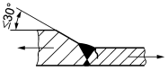
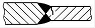
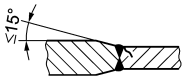
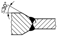
|
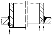
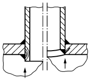
Table 3. Examples of construction types and welded connections wit the corresponding classes (K 0, K 1, K 2, K 3) and the corresponding stress factor h (depicted rupture paths exemplary) |
|||||
|
No. |
Figure |
Description |
Provision |
Class |
h |
2. Nozzle welds |
|||||
|
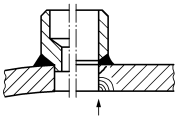
2.1 |
|
Set-through or set-in nozzle |
Welded on both sides or welded on one side with counter weld |
K 1 |
3,0 |
|
2.2 |
|
Welded on one side without counter weld |
K 2 |
|
|
|
2.3
|
|
Set-through nozzle (left type in the figure) |
Welded on both sides but not continuously welded |
K 2 |
|
|
2.4
|
Set-in nozzle (right type in the figure) |
|
K 3 |
|
|
|
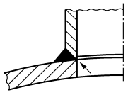
2.5 |
|
Set-on nozzle |
Welded on one side (no remaining gap), Nozzle drilled or weld root polished |
K 1 |
|
|
2.6 |
|
|
Welded on one side without counter weld or without mechanical processing of the root. |
K 2 |
|
|
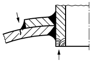
2.7
|
|
Nozzle with disk type reinforcement. Seam: at outside diameter of the disk |
|
K 3 |
|
|
2.8 |
Nozzle with disk type reinforcement. Seam: Nozzle weld |
Joint of nozzle pipe with shell and reinforcement disk welded |
K 1 |
|
|
|
Table 3. Examples of construction types and welded connections wit the corresponding classes (K 0, K 1, K 2, K 3) and the corresponding stress factor h (depicted rupture paths exemplary) |
|||||
|
No. |
Figure |
Description |
Provision |
Class |
h |
|
3. Flanges, block flanges and bolts |
|||||
|
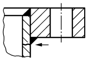
3.1 |
|
Welding neck flange |
Welded on both sides or welded on one side with counter weld |
K 1 |
2,0 |
|
3.2
|
|
Welded on one side without counter weld |
K 2 |
|
|
|
3.3 |
|
Slip-on weld flange |
Weld according to AD-Merkblatt B 8, Table 1 |
K 2 |
3,0 |
|
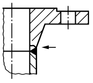
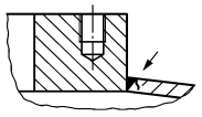
3.4 |
|
Set-in block flange |
Welded on both sides or welded on one side with counter weld |
K 1 |
|
|
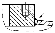
3.5 |
|
|
Welded on both sides but not continuously welded |
K 2 |
|
|
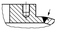
3.6 |
|
Set-in block flange with welding hub |
Welded on both sides or welded on one side with counter weld |
Kl |
|
|
3.7 |
|
Set-on block flange. Weld at inside diameter (left weld in the figure) |
|
K 3 |
4,0 |
|
Set-on block flange. Weld at outside diameter (right weld in the figure) |
|
K 2 |
|
||
|
3.8 |
|
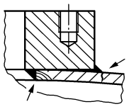
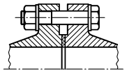
Bolts of flanged connections:
As a rule a proof is only required, if the bolts are loosened frequently. In this cases the values in brackets K 0 und h = 5,0 are valid |
(K 0) |
(5,0) |
|
|
Table 3. Examples of construction types and welded connections wit the corresponding classes (K 0, K 1, K 2, K 3) and the corresponding stress factor h (depicted rupture paths exemplary) |
|||||
|
No. |
Figure |
Description |
Provision |
Class |
h |
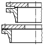
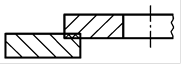
4. Bolted, attached or clamped flat plates with openings Range of validity and supplementary notes: - Stress factors h are valid for ends with central openings if the following conditions for the opening are fulfilled: (Terms s. AD-Merkblatt B 5 and B 9): di / D1 £ 0,2 and ss / s ³ 1,25 × di / D1 + 0,1 for reinforced openings and di / D1 £ 0,2 for unreinforced openings - reinforced openings weld and class assignment as numbers 2.1-2.6, 3.3-3.7 - unreinforced openings (flat plates without weld): Class K 0 |
|||||
|
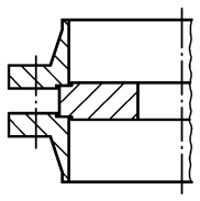
4.1
|
|
Bolted plates with and without peripheral momenmt |
s. " Range of validity and supplementary notes " for No. 4
|
K0-K3 |
3,0 |
|
4.2
|
|
Plate attached from the internal or external side |
|||
|
4.3 |
|
Simply supported flat plate
|
|||
|
Table 3. Examples of construction types and welded connections wit the corresponding classes (K 0, K 1, K 2, K 3) and the corresponding stress factor h (depicted rupture paths exemplary) |
||||||
|
No. |
Figure |
Description |
Provision |
Class |
h |
|
5. Joint weld of flat ends Range of validity and supplementary notes: Classes K and stress factors h are also valid for ends with central openings if the following conditions for the opening are fulfilled: (Terms s. AD-Merkblatt B 5 and B 9):: di / D1 £ 0,2 and ss / s ³ 1,25 × di / D1 + 0,1 for reinforced openings and di / D1 £ 0,2 for unreinforced openings |
||||||
|
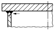
5.1 |
|
Welded end |
Welded on both sides |
K1 |
5,0 |
|
|
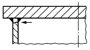
5.2 |
|
|
Welded on both sides but not continuously welded |
K2 |
|
|
|
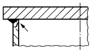
5.3 |
|
|
Welded on one side without counter weld |
K3 |
||
|
5.4 |
|
Welded end with relief groove |
Welded on one side, Groove dimensions acc. to AD-Merkblatt B 5, Table 1, Type 6 |
K2 |
4,0 |
|
|
5.5 |
|
End welded to a welding neck flange or slip-on flange |
Welded on both sides with fillet welds |
K2 |
5,0 |
|
|
5.6
|
|
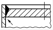
Welded end |
Welded on both sides or welded on one side with counter weld
|
K1 |
|
|
|
5.7 |
|
|
Welded on both sides but not continuously welded |
K2 |
|
|
|
5.8 |
|
|
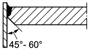
Welded on one side |
K3 |
|
|
|
5.9 |
|
Partially welded end |
Welded on one side |
K3 |
5,0 |
|
|
5.10
|
|
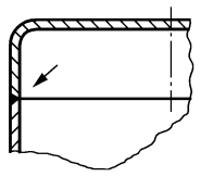
End with knuckle Joint weld |
Knuckle radius and skirt height acc. AD-Merkblatt B 5,Table 1, type a, Weld and class assignment as number 1.1-1.3 |
Kl/K2 |
1,5 |
|
|
5.11 |
End with knuckle, Knuckle |
Not welded |
K0 |
2,0 |
||
|
5.12 |
|
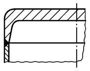
Forged or pressed end |
Knuckle radius and skirt height acc. AD-Merkblatt B 5,Table 1, type b, Weld and class assignment as number 1.1-1.3 |
K1/K2 |
1,5 |
|
|
5.13 |
Forged or pressed end, Knuckle |
Not welded |
K0 |
4,0 |
||
|
Table 3. Examples of construction types and welded connections wit the corresponding classes (K 0, K 1, K 2, K 3) and the corresponding stress factor h (depicted rupture paths exemplary) |
|||||
|
No. |
Figure |
Description |
Provision |
Class |
h |
6. Jacket – Joint welds |
|||||
|
6.1 |
|
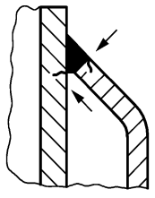
With integrated knuckle:
The evaluation is valid for the inner vessel and for the joint weld |
Welded on one side |
K 2 |
3,0 |
|
6.2 |
|
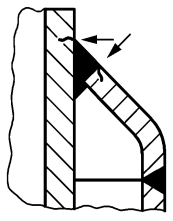
With separate knuckle: The evaluation is valid for the inner vessel wall and for the joint weld of knuckle and inner vessel wall. ( The joint weld of knuckle and outer vessel wall is classified as number 1.3 with K 2) |
Welded on both sides or welded on one side with counter weld |
K 1 |
3,0 |
|
Table 3. Examples of construction types and welded connections wit the corresponding classes (K 0, K 1, K 2, K 3) and the corresponding stress factor h (depicted rupture paths exemplary) |
||||||
|
No. |
Figure |
Description |
Provision |
Class |
h |
|
|
7. Welded attachments, general Provision: External appearance of the welds acc. DIN EN ISO 5817, classification group B, excluding the characteristics weld reinforcement, lower deviation of the weld and being non-isosceles |
||||||
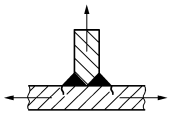
|
7.1
|
|
Welded attachments without transmitting changing tensile forces and moments
7 The evaluation refers to rib center. For the rib end, the classification is one class worse each. |
Welded on both sides |
K1 |
2,0
|
|
|
7.2 |
Welded on both sides with filet weld |
K2 |
||||
|
7.3
|
|
Welded on both sides |
K17 |
|||
|
7.4 |
Welded on both sides with filet weld |
K27 |
||||
|
7.5 |
|
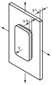
Reinforcement plate, filler plate with fillet weld joint. No transmitting of changing tensile forces and moments |
s2 £ 1,5 · s1
r ³ 2 · s2 |
K2 |
||
|
7.6
|
|
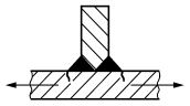
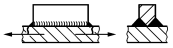
Welded attachments with transmitting changing tensile forces and moments |
Welded on both sides |
K1 |
3,0 |
|
|
7.7 |
Welded on both sides but not continuously welded |
K2 |
||||
|
Table 3. Examples of construction types and welded connections wit the corresponding classes (K 0, K 1, K 2, K 3) and the corresponding stress factor h (depicted rupture paths exemplary) |
|||||
|
No. |
Figure |
Description |
Provision |
Class |
h |
|
8. Welded attachments without transmitting of changing tensile forces or moments, examples Provision: External appearance of the welds acc. DIN EN ISO 5817, classification group B, excluding the characteristics weld reinforcement, lower deviation of the weld and being non-isosceles |
|||||
|
8.1 |
|
Vessel with skirt support |
Welded on one side |
K2 |
2,0 |
|
8.2 |
|
Vessel wall with ring support |
Welded on both sides but not continuously welded |
K2 |
2,0 |
|
8.3 |
Vessel wall with ring stiffener |
K2 |
|
||
|
8.4 |
Welded in circumferential direction but not continously welded |
K3 |
|
||
|
8.5 |
|
Vessel wall with support bracket (with or without reinforcement) |
Welded on one side |
K2 |
|
|
8.6 |
|
Vessel wall with leg support (with or without reinforcement) |
Welded on one side |
K2 |
|
|
8.7 |
|
Vessel wall with trunnion (with or without reinforcement) |
Welded on one side |
K2 |
|
|
8.8 |
|
Vessel wall with lifting lug (with or without reinforcement) |
Welded on one side |
K2
|
|
|
8.9 |
|
Vessel wall with lifting lug (with or without reinforcement) |
Welded on one side |
K2 |
|