S2 module (AD 2000 S2)
In this section of the Merkblatt, the equivalent cyclic stress range and the mean equivalent stress are calculated for unidirectional (section 5.1) and multi-axial (section 5.2) cyclic loading.
For unidirectional loading the equivalent cyclic stress range 2 σva is according to Tresca
|
(1) |
2 σa = (σ MAX − σMIN ) |
|
(3) |
σvM = 0.5 (σ MAX + σMIN ) |
With maximum stress σMAX, minimum stress σMIN and mean value σ vM.
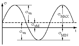
Fig. 1: Amplitude σva and mean stress σvM unidirectional
From the course of time of the main stresses you can determine the stress diefferences Δσ12, Δσ23, Δσ31;
|
(4) |
Δσ12 = σ1 − σ2, Δσ23 = σ2 − σ3, Δσ31 = σ3 − σ1, |
The equivalent cyclic stress range results in:
|
(5) |
2 σva = max[Δσ12 MAX − Δσ12 MIN , Δσ23 MAX − Δσ23 MIN, Δσ31 MAX − Δσ31 MIN ] |
The index MAX marks the greatest and the index MIN den smallest value. The equivalent mean 2 σvM results from the sum of the main stresses Σσij for the principal stresses σi and σj at the calculation of σva. You have to enter the maximum value and the minimum value of Σσij .
|
(6a) |
Σσij = σi + σj |
|
(6b) |
2 σvM = Max(Σσij) + Min(Σσij) |
For mechanical loading the equivalent cyclic stress range must be multiplied by an amplification factor. Die pseudo-elastic equivalent cyclic stress range σ*vap is
|
(7) |
2 σ*vap = 2 σvap ke |
The amplification factor can be determined per (8) and (9)
|
(8) |
ke = A1 (σvap / Rp0.2 T* −1)1/2 + 1 , |
für 1 < σvap/Rp0.2 T* < 1.5 |
|
(9) |
ke = A2 + A2 σvap / Rp0.2 T* , |
für σvap/Rp0.2 T* > 1.5 |
|
Material group |
A1 |
A2 |
A3 |
|
Ferrite, Rm=800-1000 |
0,518 |
0,718 |
0,432 |
|
Austenite, Ferrite Rm<500 |
0,443 |
0,823 |
0,327 |
|
(10) |
2 σ*vaw = 2 σvaw kv |
|
(11) |
kv = 0,7 σvaw / ( 0,5 σvaw + 0,2 Rp0.2 T* ) |
For combined loads you have to superpose the stress components from mechanical and thermal loads linearly. The pseudo-elastic stress range is per (12):
|
(12) |
2 σ*va = 2 σvap+w ke |
The allowable stress for not welded components is:
|
(13) |
2 σa zul = 2 σa fo fd fM fT* |
The allowable reference stress range 2 σa for unnotched, polished test bars made of ferritic and austenitic rolled and forged steels at ambient temperature and mere cyclic loading (average stress = 0)is for Rm < 1000 N/mm2 and 102 <= N <= 2. 106
|
(14) |
2 σa = 4. 104 / √ N + 0,55 Rm − 10 |
für (Rm < 1000 N/mm2) und (102 ≤ N ≤ 2.106) |
|
(15) |
fo = Fo(0,4343 ln N − 2)/4.301 |
für N ≤106 |
|
|
fo = Fo , |
für N ≥ 106 |
||
|
fo = 1 , |
für Rz < 6 µm |
||
|
(16) |
Fo = 1 − 0,056 (ln Rz)0,64 ln Rm + 0,289 (ln Rz)0,53 |
||
Guide values for surface roughness:
|
Surface state |
Rolled or extruded |
Mechanically processed |
Notch-free polished |
|
Rz [µm] |
200 |
50 |
10 |
|
(17) |
fd = Fd(0,4343 ln N − 2)/4.301 |
for N ≤ 2. 106 |
|
fd = Fd, |
for N ≥ 106 |
|
|
(18) |
Fd = (25 / s)1/Z , with Z= 10 , |
for s < 150 mm |
|
Fd =0.84 |
for s > 150 mm |
For forgings, you have to enter the governing heat treatment diameter per DIN 17243 as wall thickness. (s.8 Governing heat treatment diameter per EN 10222-1, Annex B)
(7.1.4a) elastic range: 2 σva < Rp0.2 T*
|
(19) |
fM = [ 1 − M(2+M) σvM / ( σa +M σa) ] 1/2, |
für −Rp0.2 T* ≤ σvM ≤ σa /(1+M) |
|
(20) |
fM = ( 1+M/3)/(1+M) − M σvM /(3 σa) , |
für σa /(1+M) ≤ σvM ≤ Rp0.2 T* |
|
(21) |
M =0,00035 Rm −0,1 |
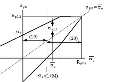
Fig. 2: Stress range as a function of mean stress acc. to Smith
(7.1.4b) Partially plastic
For Rp0.2 T* < 2 σva < 2 Rp0.2 T* or if the principal stress difference is greater than the yield strength.:
|
(22) |
Dσv = max[|Δσ12| , |Δσ23| , |Δσ31| ] > Rp0.2 T* |
The reduced equivalent stress is entered in (19) and (20):
|
(23) |
σv red = Rp0.2 T* − σva |
With the condition |σv red| <| σvM |.
Note: In the fully plastic range, the equivalent stress is reduced acc. section 6.1 and the mean stress is set to zero.
The allowable stress range for welded components is:
|
(26) |
2 σa zul = 2 σa fd fT* |
The reference stress 2 σa is
|
(27) |
2 σa = ( B1 / N )1/3 |
Factor B1 depends on the weld class (K0 to K3 in 7 Table 5 – AD 2000 S2 Table 5).
(7.2.6) For the correction factor fd Z is set to 4 in equation (18) Z = 4 and fd is limited to Fd = 0.64. For the temperature influence factor fT* equations (24) and (25) are valid.
(7.2.7) For stress-relief heat treated components with N ≥ 2. 106 the the fatigue strength increases
|
(28) |
2 σa zul = 2 σa fd fT* Max{1; 1,3 fM } |
The number of allowable load cycles Nzul is
|
(29) |
Nzul = 16 108 /( 2 σa* −0,55 Rm + 10 )2 |
Where the reference stress range σa* results from the stress range σva analogously per (13)
|
(30) |
2 σa* = 2 σva /( fo fd fM fT* ) |
As the correction factors depend on the number of allowable load cycles N, the solution must be found by iteration.
If the reference stress range is smaller than the endurance strength 2 σa* < 2 σva for N > 2 106 then there is endurance strength.
The number of allowable load cycles Nzul is
|
(31) |
Nzul = B1 /( 2 σa* )3 |
Where the reference stress range σa* results from the stress range σva analogously per (13)
|
(32) |
2 σa* = 2 σva /( fd fT* ) |
Factor B1 depends on the weld class (K0 to K3 in 7 Table 5 – AD 2000 S2 Table 5).
As the correction factors depend on the number of allowable load cycles N, the solution must be found by iteration.
For stress-relief heat treated components it is valid analogously to 7.2.7
|
(33) |
2 σa* = 2 σva /( fd fT* fM*) |
|
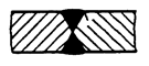
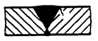
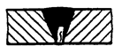
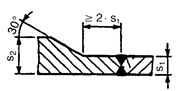
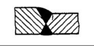
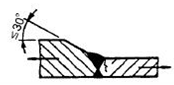
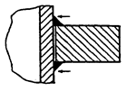
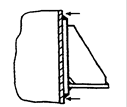
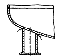
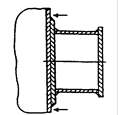
Table 5. Examples of construction types and welded connections with the corresponding weld classes (K0, K1, K2 and K3), depending on the type of stress proof (depicted rupture paths exemplary) |
||||||
|
No |
Figure |
Description |
Provision |
Weld class for stress proof |
||
|
1 |
2 |
|||||
|
1. Cylindrical and conical shells, dished ends |
||||||
|
1.1 |
|
Longitudinal or circumferential weld with equal wall thicknesses |
Welded on both sides |
K1 |
K1 |
|
|
1.2 |
|
Welded on one side with counter weld |
K2 |
K1 |
||
|
1.3 |
|
Welded on one side without counter weld |
K1 |
K2 |
||
|
1.4 |
|
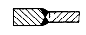
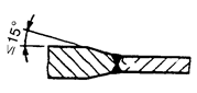
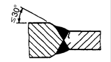
Longitudinal or circumferential weld with unequal wall thicknesses |
Welded on both sides |
K2 1) |
K1 |
|
|
1.5 |
|
K3 |
K1 |
|||
|
1.6 |
|
K1 1) |
K1 |
|||
|
1.7 |
|
Welded on both sides, Same offset of edges inside and outside |
K1 |
K1 |
||
|
1.8 |
|
K2 |
K1 |
|||
|
1.9 |
|
|
|
- |
K1 |
|
|
1.10 |
|
Cone with corner joint |
Welded on both sides or welded on one side with counter weld |
- |
K1 |
|
|
1.11 |
Welded on one side without counter weld |
- |
K3 |
|||
|
1.12 |
|
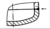
Head to shell joint for dished ends with cylindrical skirt heights acc. to AD-Merkblatt B 3 |
Stress proof 2: Description of welds, provisions and corresponding weld classes see examples number 1.1 to 1.9 |
|||

|
Table 5. Examples of construction types and welded connections with the corresponding weld classes (K0, K1, K2 and K3), depending on the type of stress proof (depicted rupture paths exemplary) |
|||||||
|
No |
Figure |
Description |
Provision |
Weld class for stress proof |
|||
|
1 |
2 |
||||||
|
2. Nozzle welds |
|||||||
|
2.1 |
|
Set-through or set-in nozzle |
Welded on both sides or welded on one side with counter weld |
- |
K1 |
||
|
2.2 |
Welded on one side without counter weld |
- |
K2 |
||||
|
2.3 |
|
Set-through nozzle (left type in the figure)
|
Welded on both sides but not continuously welded |
- |
K2 |
||
|
2.4 |
Set-in nozzle (right type in the figure) |
- |
K3 |
||||
|
2.5 |
|
Set-on nozzle |
Welded on one side (no remaining gap), Nozzle drilled or weld root polished |
- |
K1 |
||
|
2.6 |
|
|
Welded on one side without counter weld or without mechanical processing of the root. |
- |
K2 |
||
|
2.7 |
|
Nozzle with disk type reinforcement. Seam: at outside diameter of the disk |
|
- |
K3 |
||
|
2.8 |
Nozzle with disk type reinforcement. Seam: Nozzle weld |
Joint of nozzle pipe with shell and reinforcement disk welded |
- |
K1 |
|||
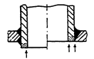
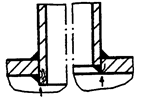
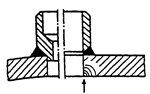
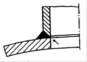
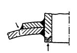
|
Table 5. Examples of construction types and welded connections with the corresponding weld classes (K0, K1, K2 and K3), depending on the type of stress proof (depicted rupture paths exemplary) |
|||||||
|
No |
Figure |
Description |
Provision |
Weld class for stress proof |
|||
|
1 |
2 |
||||||
|
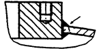
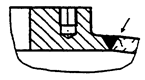
3. Flanges, block flanges and bolts |
|||||||
|
3.1 |
|
Welding neck flange |
Welded on both sides or welded on one side with counter weld |
- |
K 1 |
||
|
3.2 |
Welded on one side without counter weld |
- |
K 2 |
||||
|
3.3 |
|
Slip-on weld flange |
Weld according to AD-Merkblatt B 8, Table 1 |
- |
K 2 |
||
|
3.4 |
|
Set-in block flange |
Welded on both sides or welded on one side with counter weld |
- |
K 1 |
||
|
3.5 |
|
Welded on both sides but not continuously welded |
- |
K 2 |
|||
|
3.6 |
|
Set-in block flange with welding hub |
Welded on both sides or welded on one side with counter weld |
- |
K 1 |
||
|
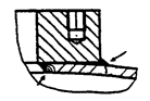
3.7 |
|
Set-on block flange. Weld at inside diameter (left weld in the figure) |
|
- |
K 3 |
||
|
Set-on block flange. Weld at outside diameter (right weld in the figure) |
- |
K 2 |
|||||
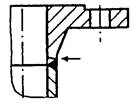
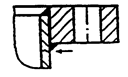
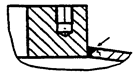
|
Table 5. Examples of construction types and welded connections with the corresponding weld classes (K0, K1, K2 and K3), depending on the type of stress proof (depicted rupture paths exemplary) |
|||||||
|
No |
Figure |
Description |
Provision |
Weld class for stress proof |
|||
|
1 |
2 |
||||||
|
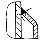
4. Jacket – Joint welds |
|||||||
|
4.1 |
|
With integrated knuckle:
The evaluation is valid for the inner vessel and for the joint weld |
Welded on one side |
- |
K 2 |
||
|
4.2 |
|
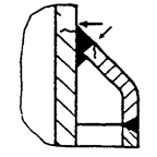
With separate knuckle: The evaluation is valid for the inner vessel wall and for the joint weld of knuckle and inner vessel wall. ( The joint weld of knuckle and outer vessel wall is classified as number 1.3 with K 2) |
Welded on both sides or welded on one side with counter weld |
- |
K 1 |
||
|
Table 5. Examples of construction types and welded connections with the corresponding weld classes (K0, K1, K2 and K3), depending on the type of stress proof (depicted rupture paths exemplary) |
||||||
|
No |
Figure |
Description |
Provision |
Weld class for stress proof |
||
|
1 |
2 |
|||||
|
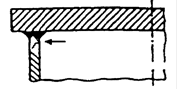
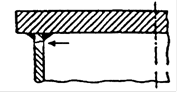
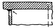
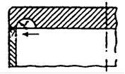
5. Joint weld of flat ends |
||||||
|
5.1 |
|
Welded end |
Welded on both sides |
- |
K 1 |
|
|
5.2 |
|
Welded on both sides but not continuously welded |
- |
K 2 |
||
|
5.3 |
|
Welded on one side without counter weld |
- |
K 3 |
||
|
5.4 |
|
Welded end with relief groove |
Welded on one side, Groove dimensions acc. to AD-Merkblatt B 5, Table 1, type e |
- |
K 2 |
|
|
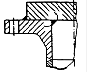
5.5 |
|
End welded to a welding neck flange or slip-on flange |
Welded on both sides with fillet welds |
- |
K 2 |
|
|
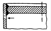
5.6 |
|
Welded end |
Welded on both sides or welded on one side with counter weld |
- |
K 1 |
|
|
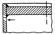
5.7 |
|
Welded on both sides but not continuously welded |
- |
K 2 |
||
|
5.8 |
|
Welded on one side |
- |
K 3 |
||
|
5.9 |
|
Partially welded end |
Welded on one side |
- |
K 3 |
|
|
5.10 |
|
End with knuckle, forged end or pressed end.
|
Knuckle radius and skirt height acc. AD-Merkblatt B 5,Table 1, types a and b, Weld and class assignment as number 1.1-1.3 |
|
|
|
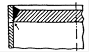
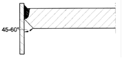
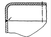
|
Table 5. Examples of construction types and welded connections with the corresponding weld classes (K0, K1, K2 and K3), depending on the type of stress proof (depicted rupture paths exemplary) |
|||||||
|
No |
Figure |
Description |
Provision |
Weld class for stress proof |
|||
|
1 |
2 |
||||||
|
6. Welded attachments, general Provision: External appearance of the welds acc. EN 25817, classification group B, excluding the characteristics weld reinforcement, lower deviation of the weld and being non-isosceles |
|||||||
|
6.1 |
|
Welded attachments without transmitting changing tensile forces and moments
2 The evaluation refers to rib center. For the rib end, the classification is one class worse each. |
Welded on both sides |
K1 |
- |
||
|
6.2 |
Welded on both sides with filet weld |
K2 |
- |
||||
|
6.3 |
|
Welded on both sides |
K2 |
K1² |
|||
|
6.4 |
Welded on both sides with filet weld |
K3 |
K2² |
||||
|
6.5 |
|
Reinforcement plate, filler plate with fillet weld joint. No transmitting of changing tensile forces and moments |
s2 ≤ 1,5 · s1 r ≥ 2 · s2 |
K2 |
- |
||
|
6.6 |
|
Welded attachments with transmitting changing tensile forces and moments |
Welded on both sides |
- |
K1 |
||
|
6.7 |
Welded on both sides but not continuously welded |
- |
K2 |
||||
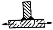
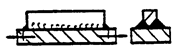
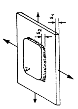
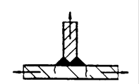
|
Table 5. Examples of construction types and welded connections with the corresponding weld classes (K0, K1, K2 and K3), depending on the type of stress proof (depicted rupture paths exemplary) |
||||||
|
No |
Figure |
Description |
Provision |
Weld class for stress proof |
||
|
1 |
2 |
|||||
|
7. Welded attachments without transmitting of changing tensile forces or moments, examples Provision: External appearance of the welds acc. EN 25817, classification group B, excluding the characteristics weld reinforcement, lower deviation of the weld and being non-isosceles |
||||||
|
7.1 |
|
Vessel with skirt support |
Welded on one side |
K2 |
- |
|
|
7.2 |
|
Vessel wall with ring support |
Welded on both sides but not continuously welded |
K2 |
- |
|
|
7.3 |
Vessel wall with ring stiffener (external pressure) |
K2 |
- |
|||
|
7.4 |
Welded in circumferential direction but not continuously welded |
K3 |
- |
|||
|
7.5 |
|
Vessel wall with support bracket (with or without reinforcement) |
Welded on one side |
K2 |
- |
|
|
7.6 |
|
Vessel wall with leg support (with or without reinforcement) |
Welded on one side |
K2 |
- |
|
|
7.7 |
|
Vessel wall with trunnion (with or without reinforcement) |
Welded on one side |
K2 |
- |
|
|
7.8 |
|
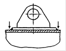
Vessel wall with lifting lug (with or without reinforcement |
Welded on one side |
K2 |
- |
|
|
7.9 |
|
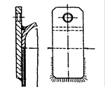
Vessel wall with lifting lug |
Welded on one side |
K2 |
- |
|
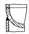
|
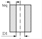
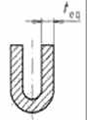
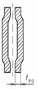
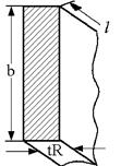
DIN EN 10222-1 Table B1; Equivalent thickness teq for cross sections differing from governing shape of cross section |
|||||||||
|
Bars |
Disks |
Rings |
Cylindrical hollow profiles with open ends |
Cylindrical hollow profiles closed at both ends |
Other |
Thickness tR of governing rectangular cross section |
|||
|
|
|
|
|
|
|
|
|
||
|
teq ≈1,5 tR |
teq ≈ 1,2 tR |
teq ≈ tR |
h>teq, |
D1> 200mm teq ≈ tR |
200mm >D1 > 80 mm teq ≈ 0,85 tR |
D1 < 80 mm teq ≈ 0,75 tR |
teq ≈ 0,6 tR |
|
b >2 tR, l > 4 tR |
|
25 |
20 |
16 |
16 |
16 |
15 |
12 |
10 |
In agree-ment. 8.3.2 |
16 |
|
50 |
40 |
35 |
35 |
35 |
30 |
25 |
20 |
35 |
|
|
75 |
60 |
50 |
50 |
50 |
40 |
35 |
30 |
50 |
|
|
100 |
80 |
70 |
70 |
70 |
55 |
50 |
40 |
70 |
|
|
150 |
120 |
100 |
100 |
100 |
85 |
75 |
60 |
100 |
|
|
200 |
160 |
130 |
130 |
130 |
115 |
100 |
80 |
130 |
|
|
250 |
200 |
160 |
160 |
160 |
140 |
125 |
100 |
160 |
|
|
300 |
250 |
200 |
200 |
200 |
170 |
150 |
120 |
200 |
|
|
375 |
300 |
250 |
250 |
250 |
210 |
180 |
150 |
250 |
|
|
500 |
400 |
330 |
330 |
330 |
280 |
250 |
200 |
330 |
|
|
600 |
480 |
400 |
400 |
400 |
340 |
300 |
240 |
400 |
|
|
750 |
600 |
500 |
500 |
500 |
425 |
375 |
300 |
500 |
|
|
Example, Line 1: The heat treatment
diameter of teq = 25 mm with a circular profile is equivalent to a
rectangular profile with |
|||||||||