S33
Please consider additional loads such as wind and earthquakes, but also torsional moments from agitators.
IMPORTANT: These additional loads must be verified for both conditions (depressurized and pressurized), if applicable.
The internal pressure is varied from 0 bar to 20 bar. As the pressure increases, the equivalent stress initially decreases because the internal pressure has a supporting effect. The equivalent stress reaches a minimum at approx. 7 bar. After this, the equivalent stress increases again, as the compressive stress now becomes dominant.

(Created with LV Atlas option 'Parameter study')
from: Eberhard Wegener, Festigkeitsberechnung Verfahrenstechnischer Apparate, Wiley-VCH Verlag GmbH Weinheim 2002
Vertical apparatuses placed on foundations are equipped with supporting feet. These can be made of tube, vertical or inclined, with or without reinforcing plate on the curved base, or of sectional steel, with reinforcing plate welded to the cylindrical shell. DIN 28 081 T. 1 to DIN 28 081 T4 apply to apparatus feet, with DIN 28 081 T. 1 being restricted to vertically arranged support feet made of tube.
The dimensions of the supporting tubes, the reinforcing plate, the base plate and their anchoring, which are part of the apparatus diameter, are specified in DIN 28 081 T. 1. The standard design is 4 supporting feet, which can be extended if necessary depending on the total weight of the apparatus with additional loads, but they must be located on the same pitch circle diameter and have a minimum distance of
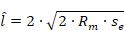
between the reinforcing plates. The spacing also applies mutatis mutandis to nozzles in the tank bottom. DIN 28 081 T. 3 contains the maximum weight forces for apparatus feet made of pipe with reinforcing plate in the area of application

under static load. The welds between the reinforcing plate and the floor are designed as fillet welds and must be designed so that they can transmit the forces corresponding to the wall thicknesses. The thickness of the reinforcing plate is to be determined with the total weight actually occurring.
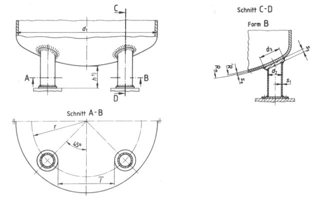
Fig. 11.31 Geometry data for determining the load-bearing capacity of arched floors loaded by supporting feet