EN 16.14 module
The EN 16.14 module calculates the minimum thickness of a cylindrical shell subject to a combination of loads in addition to pressure, at sections remote from the area of application of local loads and from structural discontinuities acc. to DIN EN 13445-3, section 16.14. There are three options:
1. Permissible individual loads (section 16.14.4)
2. Cylinder under internal pressure (P>0, section 16.14.6)
3. Cylinder under external pressure (P<0, section 16.14.7)
The permissible individual loads (1) can be used for calculating vessels on saddles. You can use the interaction condition for combined loads to check the stability. You can calculate the required wall thickness for cylinders under internal pressure and additional global loads (2). Option 3 checks the stability of cylinders under external pressure with additional loads.
The additional global load is composed of the force F and the bending moment M. For statically determined ends, the total force F is defined as:
|
|
(16.14-1) |

with the additional force Kraft Fadd without internal pressure and the design pressure P (P<0 for external pressure). For statically undetermined systems, the axial force can be determined with statically allowed assumptions.
For vertical vessels the force F includes the weight in the considered cut and the content. The moment M comprises wind load and dead load.
When calculating the compressive stress, you have to consider a possible pressure drop.
For horizontal vessels on saddle supports acc. to section 16.8 of DIN EN 13445-3 the following strength condition is valid:
|
|P|/Pmax+|Mi|/Mmax+Feq/Fmax+(Qi/Qmax)²≤1,0 |
(16.8-28) |
The maximum individual loads Pmax and Mmax are taken from equations (16.8-13) and (16.14-3). The allowable compressive force Fmax i staken from (16.14-2) and the maximum shear force Qmax is for cylinders with

|
|
(16.8-30) |

and for cylinders with

|
|
(16.8-31) |
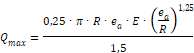
R = D/2 = mean shell radius
L = shell length including cylindrical skirt
ea = calculation thickness (without allowances)
E = Young’s modulus
The required wall thickness ereq of a cylindrical shell acc. section 7.4 is:
|
|
(7.4-2) |

The circumferential stress due to internal pressure is
|
|
(16.14-7) |

Calculation scheme
1. Select a value ea > ereq acc. equation (7.4-2),
2. Check if smax £ f, with (16.14-4).
3. If smin > 0, proceed with step 7.
4. Calculate sc,all ‘acc. equation (16.14-20).
5. Check if sc £ sc,all
6. Check if sp +sc £ sc,all
7. The design is allowed if all conditions are fulfilled. If not, the calculation must be performed again with a greater wall thickness ea.
The external pressure Pe is
|
|
(16.14-11) |

The circumferential compressive stress is
|
|
(16.14-12) |

Calculation scheme
1. Select a value ea acc. section 8
2. Check if smax +sp £ f
3. If smin > 0 proceed with step 6.
4. Calculate the maximum allowable external pressure Pe,max without any further loads from section 8 and sc,all ‘acc. equation (16.14-20)
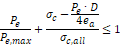
5. Check if
|
|
(16.14-14) |
6. The design is allowed if both conditions are fulfilled. Otherwise, the wall thickness must be increased and the calculation must be performed again.
The external pressure P must fulfill the following conditions:
|
|
(8.5.2-8) |

with the safety factor S=1.5 acc. equation (8.4.4-1). If pr is too small, the wall thickness must be increased or the shell stiffened.
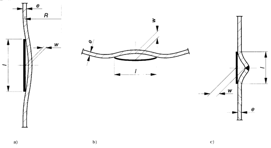
Figure 16.14-1 ― Templates for checking tolerances