UG37-e
Taken from: James R, Farr and Maan H. Jawad, Guidebook for the Design of ASME section VIII Pressure
Vessels, 4th edition, ASME Press 2010
4.5 OPENINGS IN FLAT PLATES AND COVERS
Rules for compensation or reinforcement required for openings in flat plates and covers are given in UG-39 of VIII-1. Single, small openings which do not exceed the size Iimits UG-36(c)(3)(a) & (b) and are not greater than one-fourth the plate or cover diameter are integrally reinforced and do not require reinforcement calculations.
Note: Particular care should be taken when standard blind flanges are used so as to not exceed the opening size permitted by the Standard. When the opening size exceeds these Iimits, the pressure/temperature ratings are no Ionger valid and calculations are required.
4.5.1 Opening Diameter Does Not Exceed Half the Plate Diameter
For a single opening when the opening diameter does not exceed half the plate diameter, standard reinforcement calculations may be made, keeping in mind that the total reinforcement required is:
|
|
(4.14) |

where,
Ar = required area of reinforcement, in.²
d = opening diameter in the flat plate, in.
tr = minimum required thickness of the flat plate, in.
tn = minimum required thickness of nozzle, in.
fr1 = Sn/Sh ≤ 1.0 for nozzle inserted thru flat plate and 1.0 for nozzle abutting flat plate
Sn = allowable stress of nozzle, psi
Sh = allowable Stress of flat plate, psi
The reason for the factor of 0.5 instead of 1.0 is that, unlike the situation in cylindrical shells and formed heads, the stress distribution through the thickness of a flat plate is primary bending stress instead of primary membrane stress.
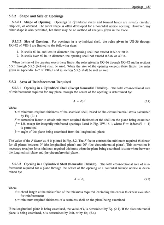
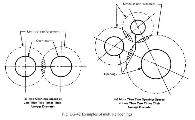
For multiple openings in which no diameter is greater than half the plate diameter, no pair of openings has an average diameter greater than one-fourth the plate diameter, and the spacing between pairs of openings is no less than twice the average diameter, Eq. 4.14 for the minimum required thickness of a plate with a single opening may be used. If the spacing between pairs of openings is less than twice the average diameter, but not less than 11/4 the average diameter, the amount of reinforcement is calculated by adding the required reinforcement of the pair to no less than 50% of the required reinforcement between the pair. If the spacing is less than 11/4 the average diameter, U-2(g) applies. In all cases, the width of the Iigament between the pair of openings shall be no less than one-fourth of the diameter of the smaller of the pair, and the edge Iigament between an opening and the edge of the plate shall be no less than one-fourth of the diameter of that opening.
In VIII -1, as an alternative to the rules for reinforcement of a single opening, the following procedure may be used to determine the minimum required thickness of a flat plate.
1. In Eqs. (4.1) and (4.3), a value of 2C or 0.75, whichever is less, may be used, except for sketches (b-1), (b-2), (e), (f), (g), and (i) of Fig. 4.1, for which 2C or 0.50, whichever is less, must be used.
2. In Eqs. (4.12) and (4.13), the quantity under the square root sign must be doubled before solving for t.
As an alternative to the rules for multiple openings, when the spacing for all pairs of openings is equal to or greater than twice the average diameter of that pair, the alternative rules for single openings may be used.
When the spacing is less than twice but equal to or more than 11/4 the average diameter of the pair, the required plate thickness shall be determined by the alternative rule for single openings multiplied by a factor,
h, that is defined as
|
|
(4.15) |
|
|
(4.16) |


where
e = smallest Iigament efficiency of all pairs
p = center-to-center spacing of a pair to get e
davg = average diameter of the same pair to get e
Again, in all cases, the width of the Iigament between the pair of openings shall be no less than one-fourth of the diameter of the smaller of the pair, and the edge Iigament between an opening and the edge of the plate shall be no less than one-fourth of the diameter of that opening.
4.5.2 Opening Diameter Exceeds Half the Plate Diameter
When the opening is a single, circular, centrally-located opening in a circular ftat plate, the plate shall be designed according to Appendix 14 of VIII-1 or Article 4.6.4 of VIII-2.
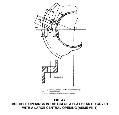
For small openings which are located in the rim of the ftat plate surrounding a large opening, as shown in Fig. 4.2, and the plate is to be analyzed according to Appendix 14, the rules in section 4.5.1 (above) for single openings and for multiple openings shall be followed, using as the minimum required thickness a plate thickness which satisfies the rules of Appendix 14. As an alternative as shown in UG-39(c)(2) of VIII-1, the thickness determined according to Appendix 14 may be multiplied by √2 = 1.414 for a single opening in the rim or for multiple openings which satisfy the Iigament spacing for a flat plate which had its thickness set by the √2 rule.
From: 'Guidebook for the Design of ASME Section VIII Pressure Vessels' - Reinforced opening Rules’.
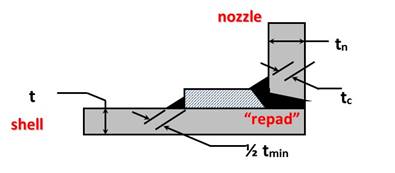
Fillet welds are generally described by leg size, (i.e. a 3/8" fillet weld has a 3/8" leg). For most fillet welds, both legs are equal!
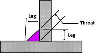
Throat Size = 0.7 x Leg Size
Leg Size = Throat Size / 0.7
·
Must be orderly and thorough.
Each step in the process is simple, but it's very easy to get confused!
· Must use the “nomenclature” UW-16.b to solve
· If there are multiple welds, each weld must be calculated separately (i.e. Fig. UW-16.1(h) has 3 weld sizes - so 3 separate calculations!)
Orientation of nozzle will be specified from Fig. UW-16.1
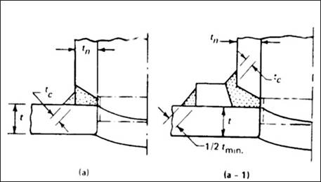
t = shell wall tn = nozzle wall
1) Find appropriate sketch in Fig. UW-16.1
a. Find correct fillet weld (if more than one shown)
b. Find dimensional symbol(s) from sketch. (e.g. tc or ½ tmin)
c. Note if the dimension illustrated is the throat or leg of the weld. (Most are throats)
2) Draw your own sketch with the appropriate symbols
3) Go to the “nomenclature”
a) Find the dimension symbol
b) Determine the calculation steps
4) Perform the calculations
5) If required, convert the Throat dimension to a Leg dimension. They normally want the weld size, which is the Leg of the weld.
(Leg = Throat/0.7)
Note! You will often have to compare thicknesses of the parts joined by the fillet being calculated. Do not be concerned with the thickness of other components, only the ones that are joined by this fillet.
The best way to learn how to determine the fillet weld size is … by doing. Here’s the problem:
A nozzle is installed per sketch Fig.
UW-16.1(a-1). Determine the required size of the fillet weld that connects the
repad (element) to the shell.
The thicknesses are:
Nozzle wall: 0.442”
Shell wall: 0.875”
Repad wall: 0.675”
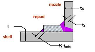
Fig. UW-16.1(a-1).
Step 1: Go the correct sketch. UW-16.1(a-1)
a) Find dimension symbol: 1/2tmin
b) Can’t solve unless we know tmin
c) Determine whether the dimension is a Throat or Leg: Throat
Step 2: Go to nomenclature (where symbols are defined).
a) Find rule:
tmin = smaller of 3/4" or thickness of thinner parts joined
b) Parts joined are: 0. 675” (repad), 0.875” (shell)
c) So tmin is smallest of: (0.750”, 0.675" or 0.875") = 0.675"
Step 4: Calculate 1/2tmin
a) 0.5tmin = 0.5 x0.675” = 0.3375”
Step 5: Convert fillet weld Throat to Leg
a) Leg = Throat/0.7 = 0.3375/0.7 = 0.482”
Note! This tmin has nothing to do with the minimum required thickness!!!
A nozzle is installed per sketch Fig. UW-16.1(a). The nozzle wall thickness is 0.375" and the shell wall is 0.625". Determine the required size of the fillet weld.
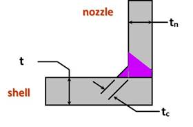
Fig. UW-16.1(a)
Step 1: Go the correct sketch. UW-16.1(a)
a) Find dimension symbol: tc
b) Determine whether the dimension is a Throat or Leg: Throat
Step 2: Go to nomenclature (where symbols are defined).
a) Find rule: tc = smaller of 1/4" or 0.7tmin
b) Can’t solve unless we know 0.7tmin, but 1st we must find tmin
Step 3: Calculate tmin
a) Find rule
tmin = smaller of 3/4" or thickness of thinner parts joined
Parts joined are: 0.375” (nozzle), 0.625” (shell)
b) So tmin is smallest of: (0.750”, 0.375" or 0.625") = 0.375"
Step 4: Calculate 0.7tmin
a) 0.7tmin = 0.7 x0.375” = 0.2625”
Step 5: Calculate tc
a) tc = smaller of 1/4" or 0.7tmin
tc is smaller of 0.250” or 0.2625” = 0.250”
Step 6: Convert fillet weld Throat to Leg
a) Leg = Throat/0.7 = 0.250/0.7 = 0.357”
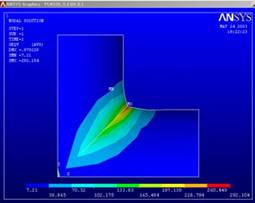
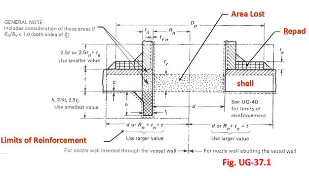
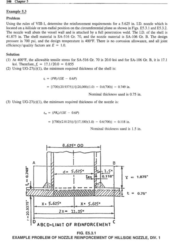
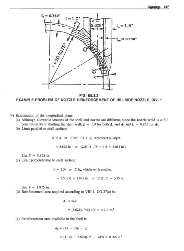
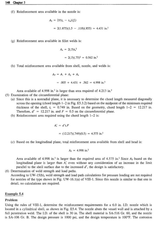
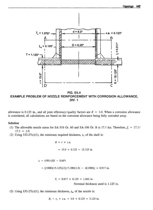
· Illustrated on Fig. UG-37.1
·
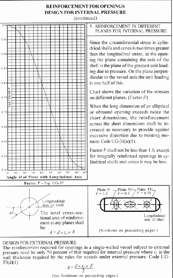
Replace Lost Area (cross sectional area) Metal (strength)
removed, must be replaced
Strength removed = Diameter x shell tmin
· Limits of Reinforcement. Extra metal must be relatively near the nozzle
· Strength of Reinforcement. Reinforcement must be same strength as that removed, or more reinforcement must be added
· Reinforcement can be obtained from multiple sources: Shell, Nozzle, Repad, Fillets. Don’t count Corrosion Allowance
Simplified Formulas
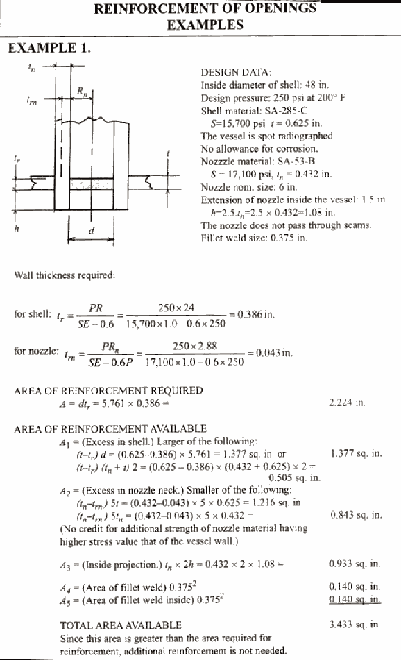
Without Reinforcing Element A1 + A2 +A41 > A
A = d x tr Area lost
A1 = d(t - tr) Shell - use larger of 2
= 2(t + tn)(t - tr)
A2 = 5t(tn-trn) Nozzle - use smaller of 2
= 5tn(tn-trn)
A41 = Leg2 Nozzle Fillet weld
With Reinforcing Element A1 + A2 +A41 +A42 + A5 > A
A, A1, A41 Same as above!
A2 = 5t(tn-trn) Nozzle - use smaller of 2
= 2(tn-trn)(2.5tn+te)
A42 = Leg2 Element Fillet weld
A5 = (Dp - d -2tn)te Element - Repad
t = shell thickness in corroded condition
tr = shell required thickness
tn = nozzle thickness in corroded condition
trn = nozzle required thickness
te = element thickness
d = diameter of nozzle in corroded condition
Dp = Outside diameter of repad