Working with a single module in pressure vessel design
The program package comprises the following modules:
|
ER06 |
Pipe components under internal pressure, straight tubes, bends, miter bends, reducers, conical shells and several joints acc. to DIN EN 13480-3 chapter 6 |
|
ER07 |
Domed heads under internal pressure acc. to DIN EN 13480-3 chapter 7.1.2 - 7.1.5 |
|
ER08 |
Openings and branches acc. to DIN EN 13480-3 chapter 8.3.4 - 8.6.3 |
|
ER11 |
Integral
attachments to metallic industrial piping acc. to DIN EN 13480-3 |
|
1591 |
Design
rules for gasketed circular flange connections and their bolting incl.
modules AFLT, SFLA, 1092, VFLN, 1514N, 269X and 159N |
The basic features and the graphical interface are identical in all strength calculation modules. Start the strength calculation program
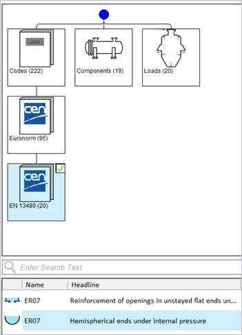
Select the module EN 07 - Cylindrical shells under internal pressure in the QuickStart menu via e.g. Codes - European standard (Euronorm) - EN 13445, and confirm the construction type "Hemispherical ends under internal pressure" in the following window.
The PROJECT module is started automatically. The delivery standards are already entered, but you may adjust them individually for one project.
Specify the calculation code and the regulation for the material definition.
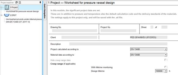
The settings are valid for the existing project and are saved with the ATL file.
Enter your design data and material data into the input mask. Input values are printed in normal black font and calculated values are printed in blue.
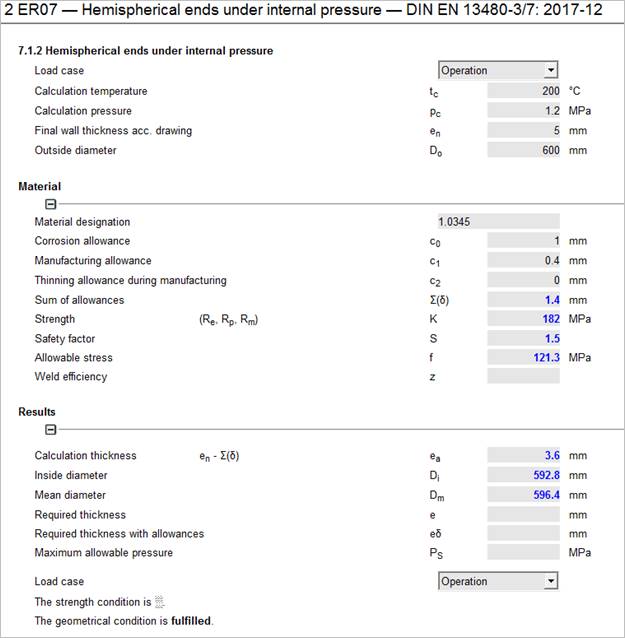
Enter the material number 1.0345 into the material field:
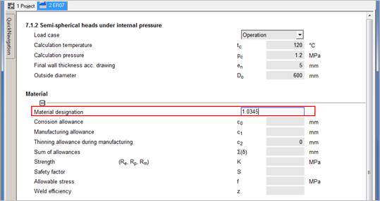
In the next field select the plate according EN 10028-2:2009 by double-click.
>> With EN 13480 an additional regulation like AD is not required.
Find the strength characteristics in the lower part of the material server. Select the desired material by double-click. The strength characteristics are transferred to the input mask.
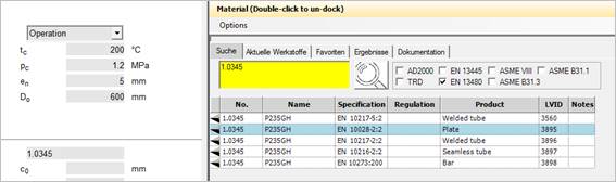
In the Documentation tab you find a detailed material documentation with characteristic values and comments from the according regulations.
This documentation can be printed out on request.
You can also select the documentation with the mouse and copy and paste it from the window for other purposes.
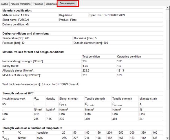
Enter the missing data. Each input value leads to possible calculations, which are performed immediately.
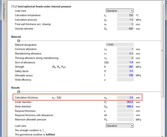
For example after having entered the material code, the calculation thickness ea is calculated at once.
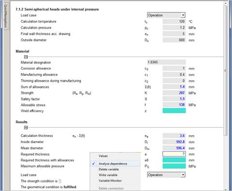
If a field has not been calculated, the required input values are missing. To see which values are required to calculate the missing value, right click on the variable and select 'Analyse dependence' or enter a 'question mark (?).
All mathematically dependent values are highlighted.
For the required wall thickness e the following state is achieved:
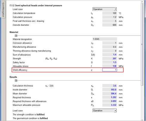
In our example it is required to enter the missing weld factor to obtain a result.
With the option "Parameter study" in the "Atlas" menu you can determine the effects of one respectively two values on a third value.
Find detailed information in the ATLAS manual.
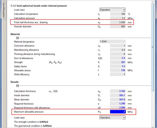
The program allows you to enter result values to obtain input values. Enter for example a maximum permissible pressure PS = 20 bar = 2 MPa to obtain the final wall thickness en with allowances. After having entered PS = 2 MPa a list with all depending variables is displayed. Clear the variable 'Final thickness".
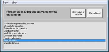
The original input value for the final wall thickness en is overwritten by the calculated value: