Strength calculations with one module
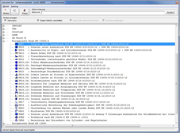
The basic functions and the graphical interface of the modules from the Strength section are compliant. Start the Strength program and select the Chapters option from the Atlas menu. In the selection screen, select the EN07 module. In the subsequent window, confirm the design "7.4.2 Cylindrical shell".
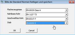
The first time you start the Strength program, you will be prompted to specify your material delivery standards.
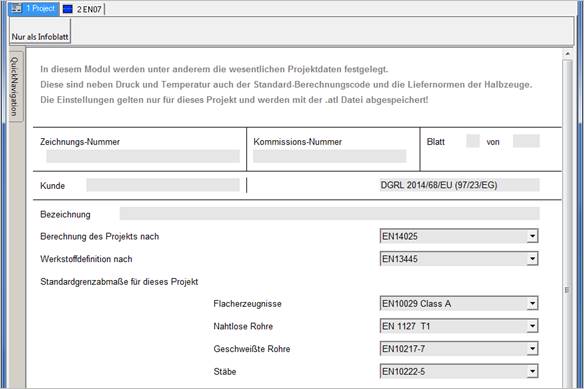
If you then select a calculation module in the strength program, the PROJECT module is automatically started. The delivery standards are already entered here, but can be adapted individually for each project.
In the PROJECT module, you now specify the calculation rule to be used and the standard according to which the material definition is to be made.
e.g. calculation according to EN 14025, but materials according to EN 13445-3
First, specify the set of rules by selecting it in the ComboBox. In our case EN 14025. Enter the design and material data in the input mask. The input values are shown here in normal font and the values calculated by the program are shown in blue.
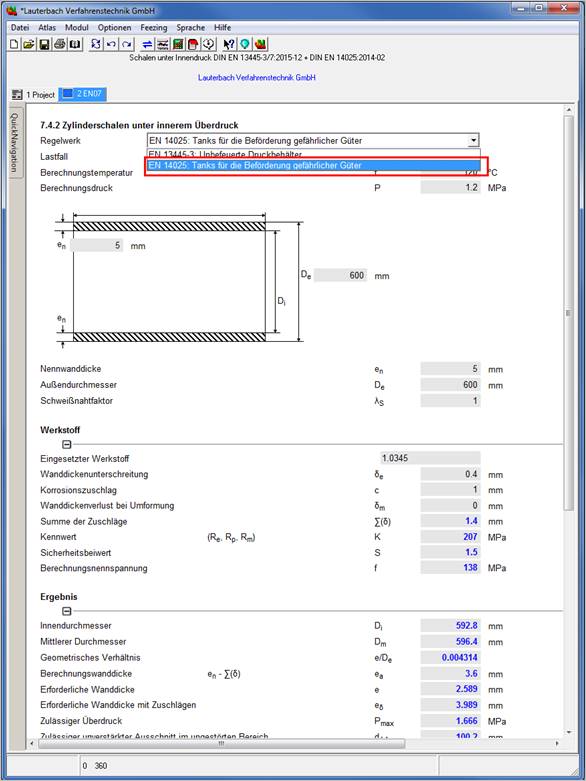
Enter the material number 1.0345 in the material input field of the input mask:
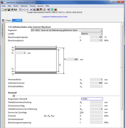
Double-click in the list box to select the plate according to delivery standard EN 10028-2:2009 without regulations - (for EN 13445, no additional regulations such as AD etc. are required):
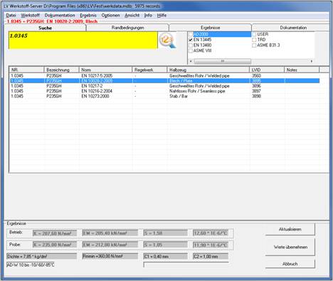
You can see the characteristic strength values in the lower area under Results. Select the desired material by double-clicking on it.
After completing the material selection, you will return to the calculation sheet. The material data has been transferred to the calculation sheet.
The Documentation tab provides you with detailed material documentation containing the material properties and comments from the relevant standards and regulations.
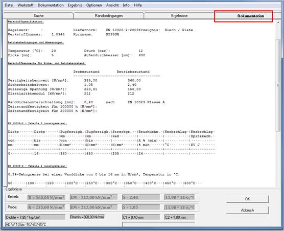
By clicking the OK button, the calculation screen is displayed again. The material data are transferred to the calculation sheet.
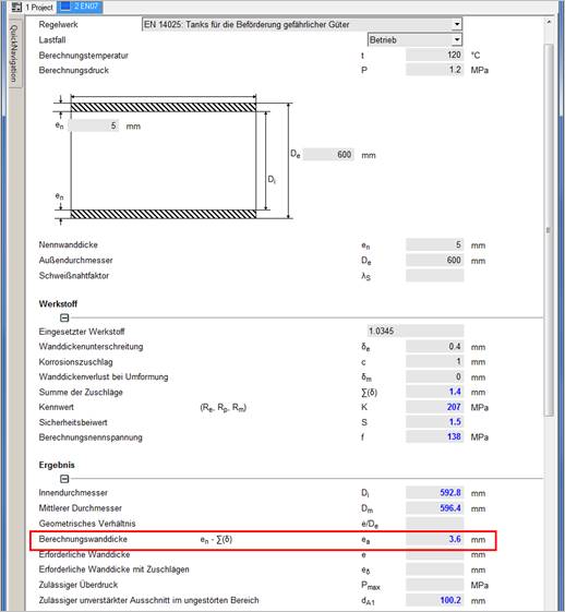
Enter the remaining data for the calculation. For each input value, possible calculations are performed immediately e.g. after entering the material, the calculation wall thickness ea is calculated immediately (see figure below).
If a field is not calculated, necessary
input values are missing. You can find out which values are missing by clicking
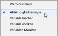
the corresponding input field with the right mouse button and selecting in the
context menu
Ask variable in the context menu.
Alternatively, you can enter a question mark (?) in the variable field of the variable to be queried. All mathematically dependent variables are highlighted in blue. The following window appears for the required wall thickness e:
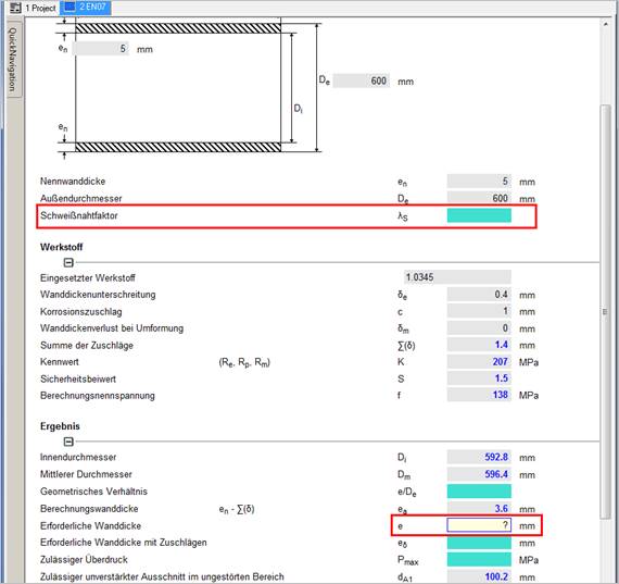
In this example, the welding seam factor is still missing to determine all missing values.
|
Which variables All dependent variables are highlighted in color. Turquoise: Influence variables Orange: Dependent variables Yellow: Variable to be examined |
|
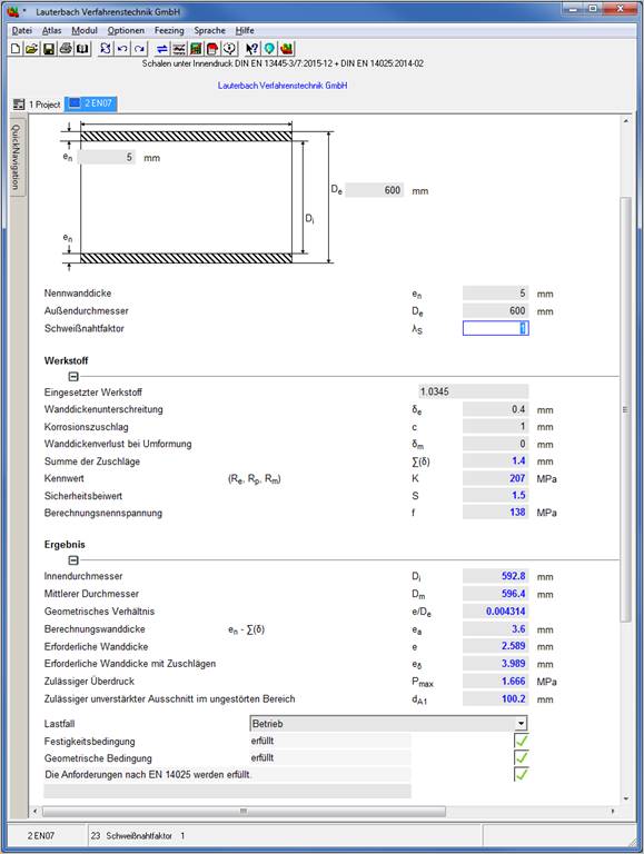
The program also offers the possibility to specify result values and to calculate back input values.
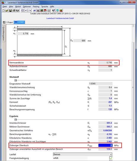
For example, you can enter a permissible maximum pressure Pmax = 2 MPa = 20 bar in the corresponding input field to calculate the required designed wall thickness en with allowances.
After entering Pmax = 2 MPa, a list of dependent variables appears, where the executed wall thickness can be cleared.
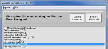
The original input value for the executed wall thickness en is overwritten with the calculated value.
Under the option Atlas / Parameter study the effect of one or two quantities on a third quantity can be determined.
See ATLAS manual "Parameter Study".