Input in 1591 module
With the 1591 module, you can calculate flanges and flanged connections of equal or different flanges.
The proof is based on the leakage method (Edition April 2014).
To obtain quick and reliable results with this method, an extensive gasket data base is included. This data base allows iterating the gasket characteristics based on manufacturers data.
Procedure:
|
Modules in the package |
Description |
|
|
1591 |
Basic module for flange calculation |
Flange calculation according DIN EN 1591-1 |
|
AFLT |
Flanges according to ASME |
Geometrical data of flanges according to ASME standards. |
|
SFLA |
Weld-neck flanges acc. |
Weld-neck flanges for pressure vessels made of stainless steels DN 300 to DN 2000 |
|
1092 |
Round steel flanges acc. |
Weld-neck flanges PN 6 to PN 100 |
|
VFLN |
Welding-neck flanges acc. |
Weld-neck flanges for vessels DN 300 to DN 3200 |
|
1514N |
Flat gaskets: Geometrical data according to Gasket characteristics acc. to DIN EN 1514-1 replaces DIN standard 2690, 2691 and 2692 |
Flat gaskets acc. to DIN EN 1514-1 · type IBC for type A faces (without nubbin) and type B faces (with nubbin) · type TG for type C and type D faces (tongue and groove) · type SR for type E and F faces (male and female face) |
|
159N |
Gasket characteristics acc. to DIN EN 1591-2 Extensive gasket database with manufacturers’ data |
|
|
Materials |
The package includes the extensive material database with more than 4700 material records. |
|
Important:
In the PROJECT module, the calculation code and the material regulation is defined.
When loading a saved file, the material database and the calculation are set to the code saved in the file, automatically.
The corrosion allowances c2 can be considered and effects the inner diameter of the flange as well as the wall thickness of the hub and the shell. The calculation can be performed for corroded or non-corroded state. It is also possible to enter a user-defined corrosion allowance c2 .

When the button < Always calculate bolt force limits automatically > is pressed, the program does always recalculate the maximum allowable tightening bolt force. The program determines maximum allowable tightening bolt force iteratively. The force is increased until one strength criterion reaches 100% utilisation. The limiting strength criterion might be the one of the bolt, the gasket or the flange.

When you press the button < Calculate bolt force limits now >, the maximum allowable tightening bolt force is calculated immediately due to user action The program determines maximum allowable tightening bolt force iteratively. The force is increased until one strength criterion reaches 100% utilisation. The limiting strength criterion might be the one of the bolt, the gasket or the flange.
Please note:
For saving calculation time and avoiding unnecessary calculation runs, we recommend using this button. The complete calculation run is only performed on request.
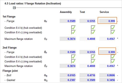
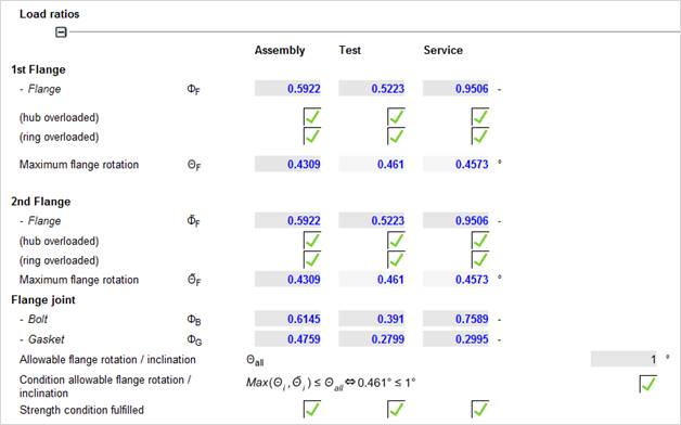
In this figure you can see the load ratios. The bolt force limits are determined to receive a utilization of the flange of ~ 100 % .

A pipeline is to be connected to a vessel with a flange. We want to check if the flange thickness of a standard flange per EN 1092 might be reduced.
The pipeline, the tube side flange and the gasket are standard parts. They have test certificates / manufacturer certificates.
A calculation of these parts is not required.
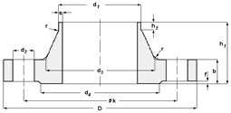
1. What is the required minimum flange thickness?
2. What is the required bolting torque?
The 1591 Calculation program creates a completely documented calculation of the flanged connection. All required values may be taken from the documentation. The required input values are for example:
|
Drawing of the vessel |
-> |
Geometrical data of the flange |
|
Drawing of the vessel |
-> |
Operating data, Pressure, Temperature |
|
Bill of material |
-> |
Geometrical data of the bolts and of the gasket |
|
Calculation standards or data bases |
-> |
Gasket characteristics, detailed bolt characteristics |
Start the strength calculation package via the start menu (Start -> Programs) or use the desktop icon. Enter 1591 into the search field and start the module by double-click or use the green start arrow.

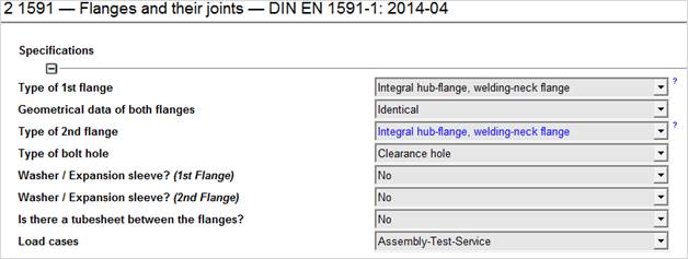
Set basic constructive specifications with selection boxes.
We select ‘Integral hub flange, welding neck flange’.
The geometry of the second flange might be the same as the first flange or it can differ from it. (e.g. blank flange)
In the Project Explorer you will also find the auxiliary modules of the different load cases. Always enter data in the main module only! You may rename the main module according to your requirements.
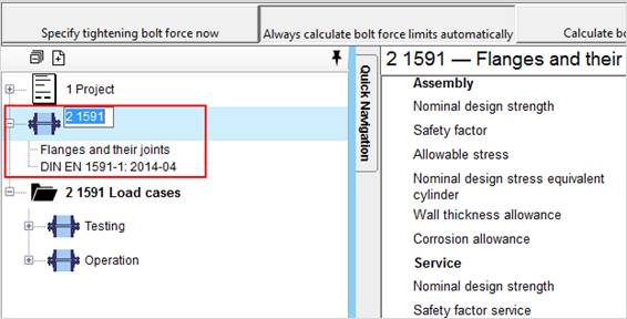
The PROJECT module is created automatically. The delivery standards are already filled in, but of course, you can adjust them individually.
Specify the calculation regulation and the material regulation in the PROJECT module.
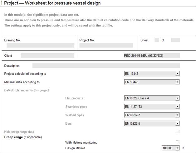
The settings are valid for the whole project and they are saved in the ATL file.
In the upper area of the input mask enter a service gauge pressure of 14 bar at an operating temperature of 200 °C.
Enter a test pressure of P’ = 20 bar. The test is performed at a temperature of 20 °C.
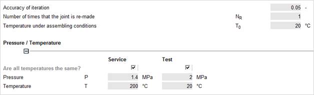
Please note
For every load case acc. EN 1591, like service and test, the program calculates the mounting case simultaneously and shows it in the input mask.
Often, the loading of the flanged connection at mounting (after bolting but at ambient temperature and without internal pressure) is higher than under service conditions.
The internal pressure decreases the pressure load in the gasket, due to a partial compensation of the pre-stressing.
The program includes a material database with many materials. There are several possibilities to select a material from the database:
· Enter the material description
· Search for a material by entering only a part of the material description
· Select from a list
· Stepwise limitation of the selection list by code, standard, or semi-finished product.
Enter the temperature of the flange (200°C) for the bolt temperature.
Different temperature or different coefficients of thermal expansion of flange and bolt may lead to great thermal elongation and result in high stresses.
For a material-saving dimensioning of the flange, the materials should have similar coefficients of thermal expansion.
Enter 1.4580 (EN10028-7) as flange material of the first flange and of the second flange and the same as shell material
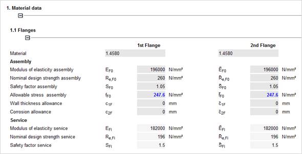
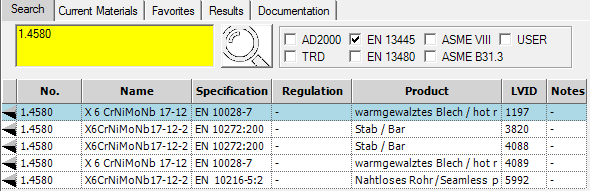
As we want to use the same material for the shell, you can simply select the material by double-clicking the entry in the material list of the InfoBrowser.
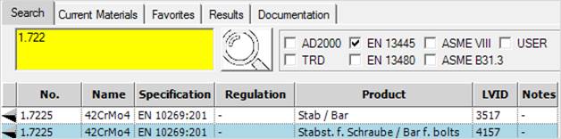
Now enter the first numbers of the material of the bolts in the input filed of the bolt material. For example, the first numbers of 1.7225 bolt made of stainless steel (1.722…).
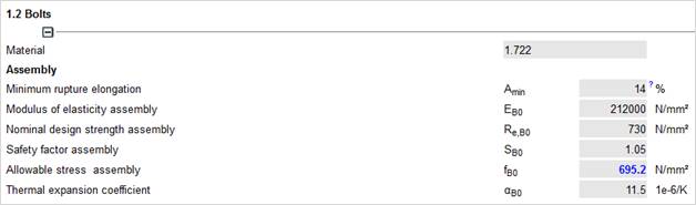
Double-click on the desired material in
the material database. For example
Bar for bolts 1.7225:
According to the drawing or the bill of material, the piping flange is a round steel flange according EN 1092-1. As the vessel flange must match the piping flange in dimensions like bolt circle, inside diameter, bolt hole diameter, etc., we select flange code EN 1092 in the input mask.
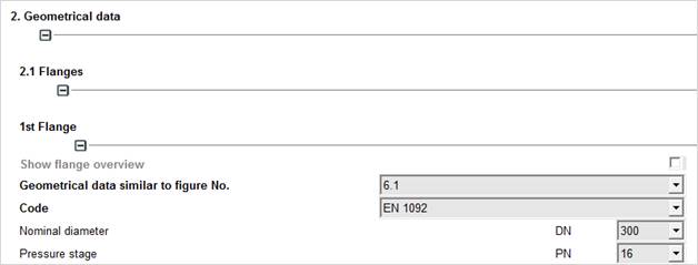
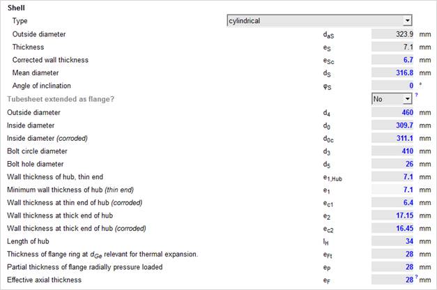
Enter figure number, pressure stage and nominal diameter and then the geometrical data of the flange are entered automatically.
Select in the field: Use leakage method? Yes
The program uses the internal gasket database with manufacturer data.
Then enter the required gasket data.
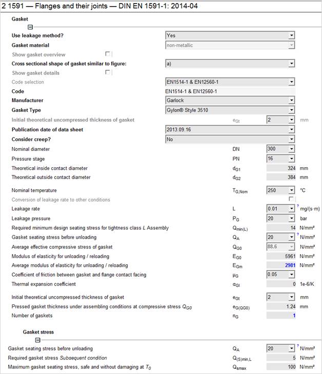
As we have specified the flange diameter, pressure stage, type and operating temperature of the gasket, most of the values are automatically entered in the input mask for the flange calculation. For example:
· Inside diameter and outside diameter of the flange
· Bolt circle diameter, number of bolts, bolt hole diameter
· Inside diameter and outside diameter of the gasket
· Minimum and maximum gasket seating stress, etc.
Complete the missing data:
Coefficient of friction of bolt thread m = 0.12
When all required data are entered, the program starts the calculation automatically.
Please note:
This is only valid, if the option < Always calculate bolt force limits automatically > is activated. < See Always calculate bolt force limits automatically>.
Then scroll down to the calculation results.
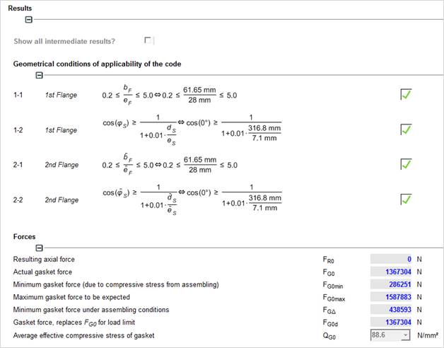
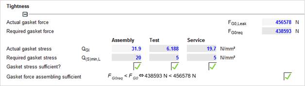
Now you can find the results in the input mask. The data are sorted as first flange, second flange, and flange joint (gasket and bolts).
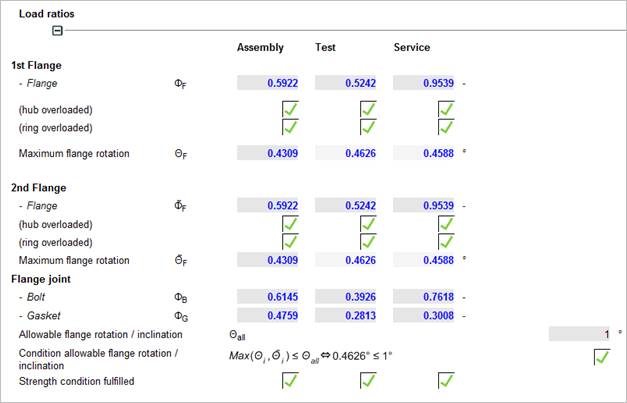
Here you see an overview of utilsation of bolt, gasket, first flange and second flange and maximum flange rotation.
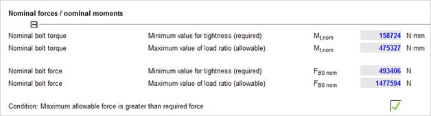
Find the allowable bolt forces in the separate section Nominal forces / nominal moments.
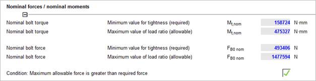
When this option is not activated:
The program determines maximum allowable tightening bolt force iteratively. The force is increased until one strength criterion reaches 100% utilisation. The limiting strength criterion might be the one of the bolt, the gasket or the flange.
When this option is activated:
Then you can enter the tightening bolt force/moment on your own. e.g. 150 Nm
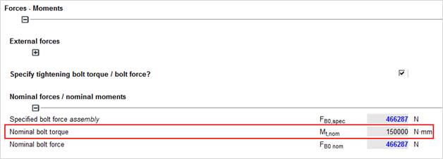
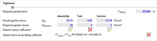
Based on this tightening force, the program calculates the load ratio and the tightness. As the minimum bolting torque for tightness is 158 Nm, the program will show that the joint is not tight enough.

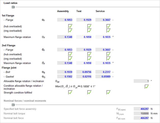
Nevertheless, the load ratios are within the allowable ranges

This option lets you determine the leakage rate with standard values deviating from the standard. This is only required in very special and singular cases.
s. Variable 90 – Leakage rate [mg/(s·m)]
Please note:
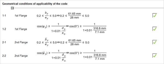
In some cases, the geometrical conditions are not fulfilled. You need to check every singular case, which condition is violated and if it is possible to change the construction to fulfil the conditions. Sometimes standard flanges according EN 1092 show a violation of geometrical conditions. Usually these deviations are allowed.
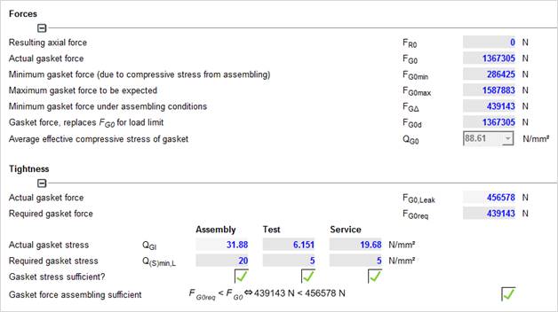
If the gasket force is insufficient, please check bolting torque. Depending on the individual case, changes at the gasket, nominal bolt diameter, number of bolts, or materials might be required.
Please note:
It might be the case, that this inequation is not fulfilled with only a minimum lower deviation due to a tolerance of the iterative process.
In this case, we recommend a recalculation by pressing ‘F7’ to check the result again.
See explanations for ‚Gasket force assembling sufficient‘.
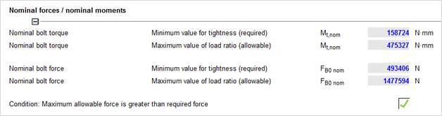
The minimum required and maximum allowable nominal bolt forces are presented in the input mask.
Please note:
When the user specifies the moment, this evaluation is omitted as the user specifies a defined case.
When calculating the flanged connection, you have to consider several different load cases. These load cases are calculated in the background module group ‘1591 Load Cases’.
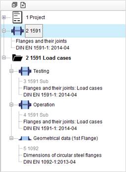
The group contains calculation for the load cases Testing and Operation, as well as the Overview on the geometrical data of the flange.
These calculations serve for a complete documentation and as a rule, the user does not have to enter values there. You can see all details of the flange calculation.