Variables
In general, it does not matter which flange you treat as 1st flange and which one as 2nd flange. The only case where it matters is when you have blind holes. Blind holes are always in the 1st flange.
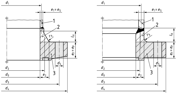
|
|
|
|
6.1 |
6.2 |
|
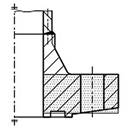
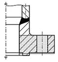
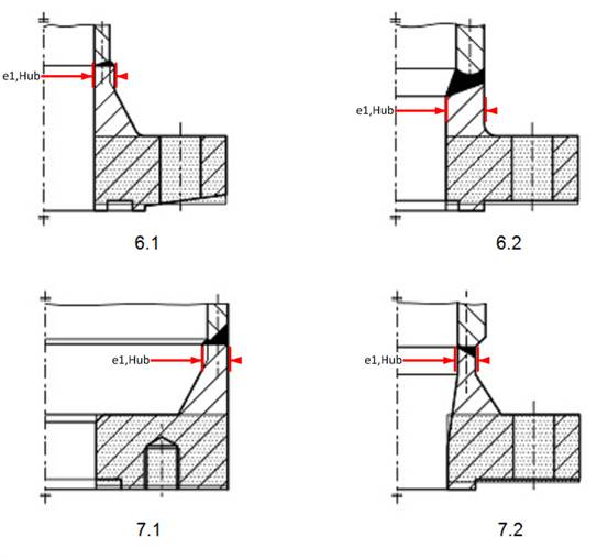
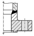
Figure 6 - Weld-neck flanges with cylindrical shells (example 1) |
|
|
|
|
|
7.1 |
7.2 |
|
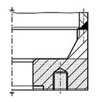
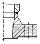
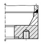
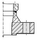
Figure 7 - Weld-neck flanges with cylindrical shells (example 2) |
|
|
|
|
|
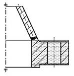
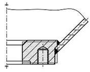
8.1 |
8.2 |
|
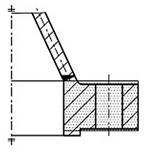
Figure 8 - Flanges welded to conical shells |
|
|
|
|
|
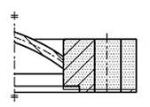
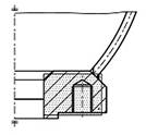
9.1 |
9.2 |
|
Figure 9 - Flanges welded to spherical shells |
|
|
|
|
|
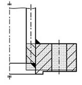
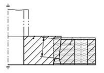
Figure 10 - Weld-on plate flange |
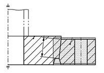
Figure 11 - Blank flange |
|
|
|
|
12.1 |
12.2 |
|
Figure 12 - Loose flanges with stub or collar |
|
|
|
|
|
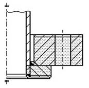
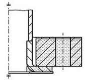
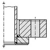
Figure 13 - Hubbed slip-on welded flange |
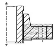
Figure 14 - Hubbed threaded flange |
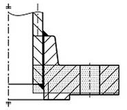
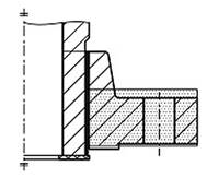
EN 1591-1 is based upon the principle that a selected leakage rate is to be achieved. In that case, the gasket sealing coefficients have to be taken from results from tests performed according to EN 13555 or directly from EN 1591-2:2008.
Conversion to different leakage rates / tightness classes (TA Luft)
|
Class A |
Class B |
|
Class C |
|
|
|
|
|
|
|
|
|
|
≤ 10-6 |
≤ 6,1 · 10-6 |
≤ 10-4 |
≤ 6,1 · 10-4 |
≤ 10-2 |
≤ 6,1 · 10-2 |
|
|
|
|
|
|
|


Conversion of mbar·l/s:
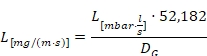
DG: average gasket diameter in mm
Conversion to other conditions (Hans-Joachim Tückmantel, Dichtungstechnik im Anlagenbau, expert Verlag 2011)
The gasket leakage behaviour is measured according to EN 13555, using Helium at 293.15 K = 20°C.
A leakage rate at another absolute Temperature T and for other media characterized by their molecular weight can be estimated, molecular flow provided, according to the following equation - as mentioned in DIN 28090-1 Annex A.7:
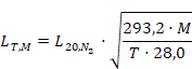
T: absolute temperature in K
M: molecular weight in kg/kmol
A conversion of gas leakages to other pressure differences ΔP than 40 bar should be done according to the following rule, recommended as well from the MPA Stuttgart:
|
For ΔP < 40 bar: |
LΔP= L·(P2-P1)/(41-1) |
|
For ΔP = 40 bar: |
LΔP= L |
|
For ΔP > 40 bar: |
LΔP= L·(P2²-P1²)/(41²-1²) |
This value has to be specified by the user. We recommend starting with the lowest value.
If one of the load case is limiting – except assembly – you can use a higher value.
Only for calculating the load limit.
Only for calculating the compliance.
Only for calculating the compliance.
Actually, it is Af/bF. In the absence of AF the actual flange thickness is used as a rule. The module calculates it like this. The value can be overwritten by the user.
Actually, it is Af/bF. In the absence of AF the actual flange thickness is used as a rule. The module calculates it like this. The value can be overwritten by the user.
Only for flanges with hub:
The minimum rupture elongation is only relevant in the following cause:
Section 8.2
Bolt load ratio:
|
|
(123) |
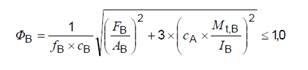
Where cA and cB defined as follows:
|
cA = 1 in assembly condition, for bolt material with minimum rupture elongation A ≥ 10 % |
(124) |
|
cA = 4/3 in assembly condition, for bolt material with minimum rupture elongation A < 10 % |
(125) |
|
cA = 0 in all other loading conditions and in assembly conditions when no torque is applied on the bolt (tensioner) |
(126) |
The value cA = 1 is based on a plastic limit criterion. Due to this criterion, some limited plastic strains may occur at periphery of the bolts in assembly condition.
Use of this criterion has been validated by industrial experience, for bolt material with sufficient ductility (A ≥ 10 %).
The value cA = 4/3 is based on an elastic limit criterion. Even with sufficiently ductile bolt material, it may be selected if a strict elastic behaviour of the bolts is wished in assembly condition.
Only for calculating the load limit.
This factor is 1 by default. It can be overwritten by the user for every single load case.
Concerning cB, it is recommended to apply nuts with specified proof load values not less than the minimum proof load values of the screws on which they are mounted (eN x fN ≥ 0,8 x dB0 x fB). If bolts are screwed in the flange, the engagement length of screws in threaded holes shall be sufficiently large (l5t ≥ 0 ,8 x dB0 x fB/fF).
These two aspects are taken into account by introducing a correction factor cB ≤ 1, determined as follows:
|
|
(127) |

In general, it does not matter which flange you treat as 1st flange and which one as 2nd flange. The only case where it matters is when you have blind holes. Blind holes are always in the 1st flange.
|
|
|
|
6.1 |
6.2 |
|
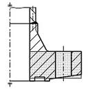
Figure 6 - Weld-neck flanges with cylindrical shells (example 1) |
|
|
|
|
|
7.1 |
7.2 |
|
Figure 7 - Weld-neck flanges with cylindrical shells (example 2) |
|
|
|
|
|
8.1 |
8.2 |
|
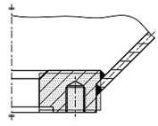
Figure 8 - Flanges welded to conical shells |
|
|
|
|
|
9.1 |
9.2 |
|
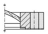
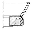
Figure 9 - Flanges welded to spherical shells |
|
|
|
|
|
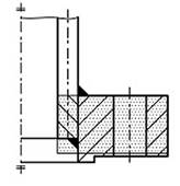
Figure 10 - Weld-on plate flange |
Figure 11 - Blank flange |
|
|
|
|
12.1 |
12.2 |
|
Figure 12 - Loose flanges with stub or collar |
|
|
|
|
|
Figure 13 - Hubbed slip-on welded flange |
Figure 14 - Hubbed threaded flange |
It has influence on the rigidity. Usual procedure: Add the total cross section area of the tube walls to the shell wall.
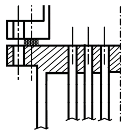
It has influence on the rigidity. Usual procedure: Add the total cross section area of the tube walls to the shell wall.