Special information
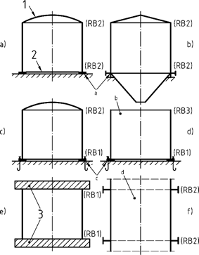
The following boundary conditions must be distinguished:
RB 1: radially and axially non-displaceable edge
RB 2: radially non-displaceable, axially displaceable edge
RB 3: free edge
See section (403) of the norm and the following graphic:
Legend
|
1 Dome or truss rod |
a) Edge not anchored |
|
2 Bottom plate |
b) open |
|
3 end plates with very high bending stiffness |
c) Edge anchored |
|
|
d) for verification of the partial shell |
Fig. 11 - Design explanations and examples of boundary conditions
Recorded boundary conditions
|
|
RB1 |
|
|
RB2 |
|
|
RB3 |
|
|
RB4 |
|
|
RB5 |
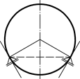
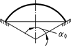
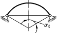
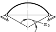
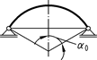
In accordance with Section 509 of the norm, a three-shot replacement circular cylinder shall be formed, the dimensions of which are the provisions of the norm.
When determining the ideal circumferential buckling stress, lengths and wall thicknesses of the replacement circular cylinder are used to calculate the coefficient according to Fig. 20 of the norm. In principle, it is recommended to compare the relevant quotients according to Section 510 of the norm with Fig. 20, since the norm only specifies curves for some of the possible combinations. It is possible to enter the coefficient manually in the input mask.
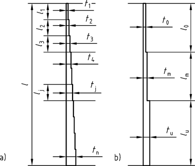
Fig.
19- Circular cylinder with stepped wall thickness a)
and three-barrel replacement circular cylinder b)
The geometry data of the cone shell can be partly calculated by the program. If three of the following five sizes are defined by the input, the remaining two sizes are calculated:
Height, length, half opening angle, radius 1, radius 2
It is recommended to comply with the assumption also made in the norm
radius 1 < radius 2
One of the two radii must be entered. The calculation of the radii is not clear, because the program does not assume that the condition specified above is fulfilled. The calculation is done without any problems if you enter the two radii first. If known, you can then enter the angle and have the two missing quantities - height and length - calculated unambiguously from it.
Other calculation methods are also possible; however, depending on the system, the calculation of the angle may take some time due to the necessary iteration.
You can see sample data here.
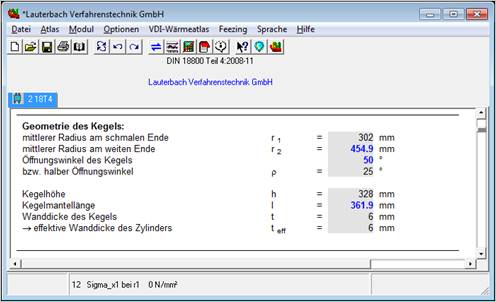
Input values are shown in black, values calculated by the program are shown in blue
The stress quantities meridian compressive stress and circumferential compressive stress vary depending on the angular coordinate in the meridian plane. Negative values for the circumferential compressive stress correspond to a circumferential tensile stress.
In accordance with Section 709 of the norm, circumferential tensile stresses must not be taken into account with their effect of increasing the buckling load.
By specifying different values for the angular coordinate meridian plane, the influence on the stress quantities can be investigated.
In the case of very short circular cylinder shells, part of the shell pressure may be absorbed by the edges. This does not apply, of course, to boundary condition 3 (free edge). The program also calculates for this boundary condition using equation 49 and the coefficient from yTable 3 of the norm. In the norm, this case (RB 3) - which should only be of practical importance in the rarest cases - is not regulated. ^