Variable list
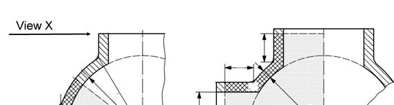
Spherical housing:
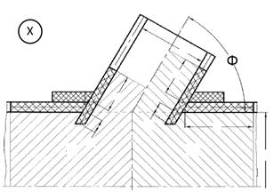
Cylindrical housing:
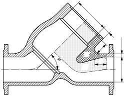
s. Calculate areas with OnShape CAD online
s. Calculate areas with OnShape CAD online
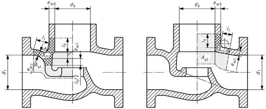
Cylindrical housing
Cylindrical housing with branch
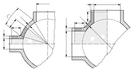
Spherical housing
s. Calculate areas with OnShape CAD online
s. Calculate areas with OnShape CAD online
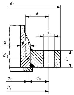
Instead of di2 you can use di in equation (190) provided the welds are fully load-bearing.
The calculation of the flanges shall be carried out in accordance with, or on the lines of, the specifications laid down in EN 1591-1 or in EN 13445-3. The calculation can however also be carried out in accordance with the formulae featured below, which are solved with respect to the thickness of the flange plate hF as a simplification.
Flanges with gaskets not in the load path can also be calculated according to this standard. Instead of the middle gasket diameter the middle metal contact diameter for the calculation of the moment arms shall be used. Characteristic gasket parameters shall be taken from the documented gasket data from the gasket manufacturer or, if unavailable, from Annex A.
|
|
|
|
a) Direct loading |
b) Not subject to direct loading |
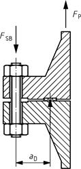
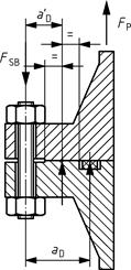
Figure 46 — Types of flange connections