Basic Equations
The allowable stress f for mainly statically loaded construction components is equal to the material strength K divided by the safety factor S
f = K/S. (6.3-1)
Table 6.3-1: Material strength K and corresponding safety factor S for forged and rolled steels with mainly statically loading under internal pressure.
|
Strength value K |
Rm bei 20°C |
Rp0,2 / tc |
Rm/T/tc (* |
|
Safety S |
2,4 |
1,5 |
1,25 |
*) T is the minimum service life time, T > 100.000 hours. If the correct life time is not known use: T=200.000h. In exceptional cases with short loading (e.g. purging) T = 10.000 hours.
If only values for T=100.000 hours exist, the safety factor S=1.5 must be used.
When the creep characteristics for fully loaded weld seams are not available, the strength values for the basic material must be reduced by 20%, if they are used for the calculation of weld constructions with fully loaded weld seams. (e.g. axially welded pipe).
For austenitic steels with Rp0,2/Rm < 0.5 at 20 °C the yield strength Rp1,0/tc (1% offset) can be used instead of Rp0,2/tc (0.2 % offset).
Table 6.3-2: Criteria for the design strength K and the corresponding safety factor S for cast iron and cast steel according to requirements of section 2 of the standard.
|
|
Strength K |
Rm Rupture at 20°C |
Rp0,2 / tc yield |
Rm/T/tc rupture at tc |
|
|
Safety factors S |
Cast steel |
3,2 |
2,0 |
2,0 |
|
|
Cast iron with spherical graphite |
Heat treated |
2,0 |
3,0 |
4,0 |
|
|
Not heat treated |
2,0 |
- |
- |
||
The allowable stress for test pressure is
f' = K'/S'. (6.3-2)
Table 6.3-3: Strength value K' and allowable safety factor S' for test pressure p'
|
Safety factor S' |
|||
|
Strength K' |
Rolled and welded steels |
Cast steel |
Cast iron with spherical graphite |
|
Rp0,2 at t = 20 °C |
1,1 |
1,4 |
2,2 |
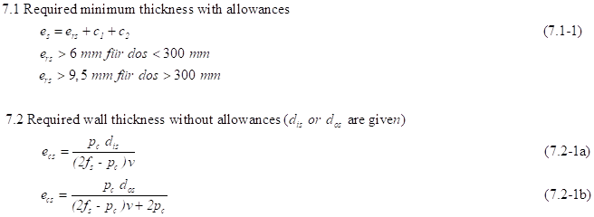
The required wall thickness of cylinders is defined in sections 7.1 and 7.2. Below follows the required wall thickness with allowances (7.1-1) and the required thickness for internal pressure without allowances
The weakening of the basic body can be compensated a) by an increased thickness of the basic body or b) a thick walled nozzle.
a) Increased wall thickness of the basic body on a minimum length of lrs.
b) Increased wall thickness erb of the nozzle on a minimum length of lb1; conditions for erb/ers:
|
dib |
dib/dis |
erb/ers |
|
<50mm |
|
<2 |
|
>50mm |
<0.2 |
<2 |
|
>0.2 |
<1 |
|
|
|
|
|
c) Thickening in the opening region (Forging, cutting)
d) Reinforcement plates
Symbols:
|
dib |
Inside diameter of the nozzle |
|
dis |
Inside diameter of the shell |
|
erb |
Calculation thickness of the nozzle |
|
ers |
Calculation thickness of the shell |
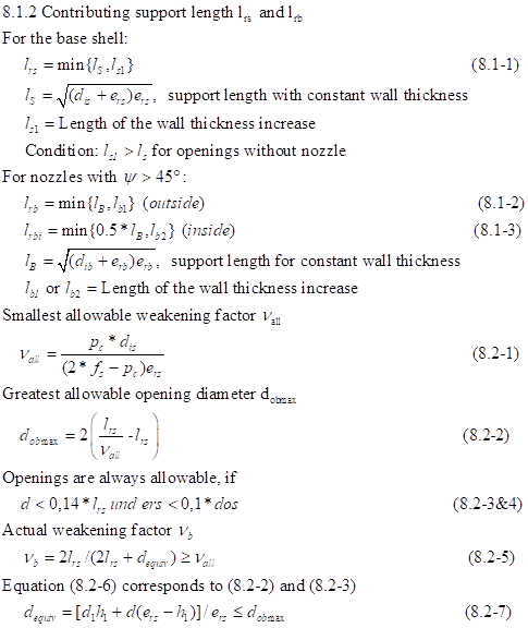
For different variants of design type 1, the diameter d and depth h1 can be so selected that the equivalent diameter in Eq. (8.2-7) corresponds with the required value in the European norm, see also Fig.2 to Fig. 6.
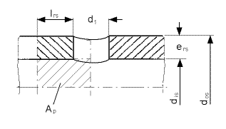
Fig. 2: Single opening with d1=d=opening diameter (Fig. 8.2-1 European norm 12952-3)
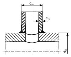
Fig. 3: Attached nozzle (d1=nozzle outside diameter)
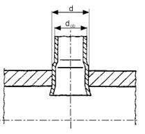
Fig. 4: Roller expanded and seal welded pipe
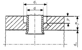
Fig. 5: Roller expanded pipe with graded hole
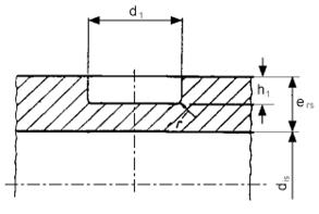
Fig. 6: Partial drill hole (d=0)
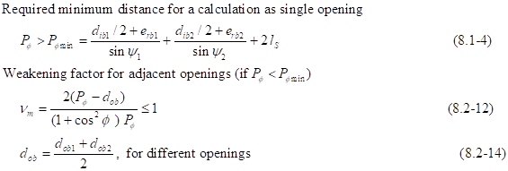
Adjacent openings can be calculated as single branches when the distance Pφ is larger than the theoretical support length given by eq. (8.1-4). Otherwise, the combined weakening factor νm can be calculated with eq. (8.2-12).
Section 8.3 of the Euronorm considers also the support effect of the nozzles. The calculation is performed in design type 2 with five variants according to Figure 7.
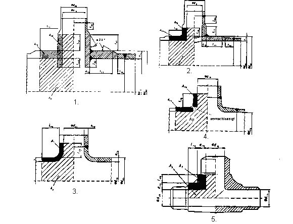
Fig. 7: Variants of the vertical nozzle of design type 2:
1 Set through nozzle with seal welding; 2 Set on nozzle; 3 Welded nozzle attached at extruded cylinder; 4. Conical transitions and roundings; 5 Integral branch.
The detailed Figures for the variants are illustrated in Figures 8 to 12. Equations (8.3-2) and (8.3-4) for the allowable stress of the shell can be written in the form

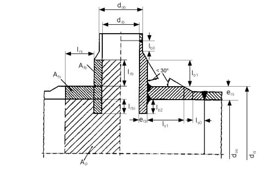
Fig.8: Set through nozzle with seal welding.
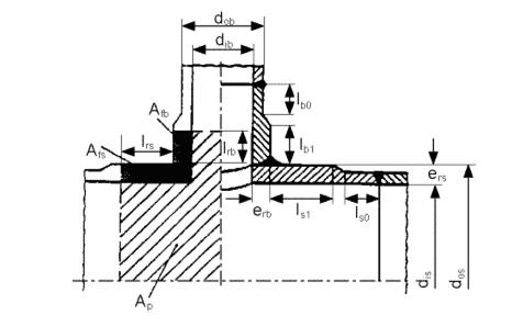
Fig.9: Set-on nozzle
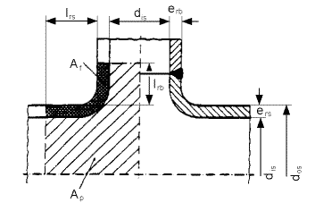
Fig.10: Welded nozzle attached at extruded cylinder
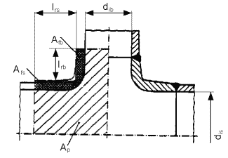
Fig.11: Conical transitions and roundings
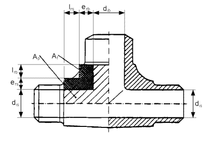
Fig.12: Integral branch
The strength conditions for the calculated circumferential stress fa on the left and right side of the opening are
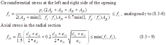
The variables fs and fb signify the allowable stress in the shell and nozzle, respectively.
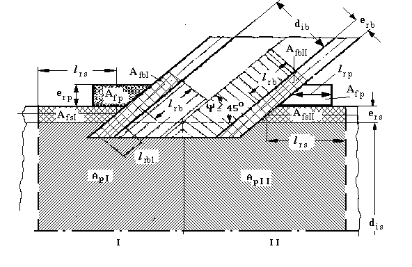
Fig.13: Single openings with oblique nozzle and reinforcement (design type 3)
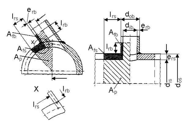
Fig. 14: Loading diagram for a cylindrical shell with non-radial branch
The strength condition (8.3-2) holds, with the areas according to Fig. 14. For design type 4, one or two non-radial branches can be selected. When a single branch is calculated, the values for branch II will not be considered. Different additional variables for the calculation are illustrated in Fig.19.
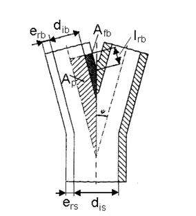

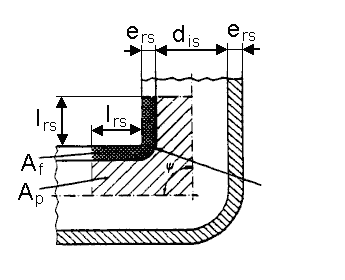
Fig.16: Forged and drilled integral branches.
For this type of integral branch holds Eq. (8.3-10) for design type 5 with y=1.
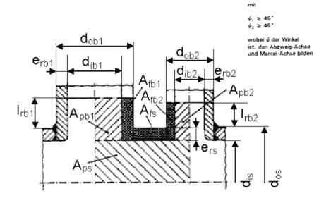
Fig. 17a: Loading areas in the axial section.
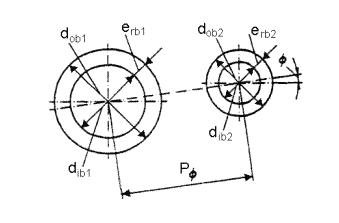
Fig.17a&b: Loading diagram for cylindrical shells with adjacent nozzles placed at an angle f to the shell axis.
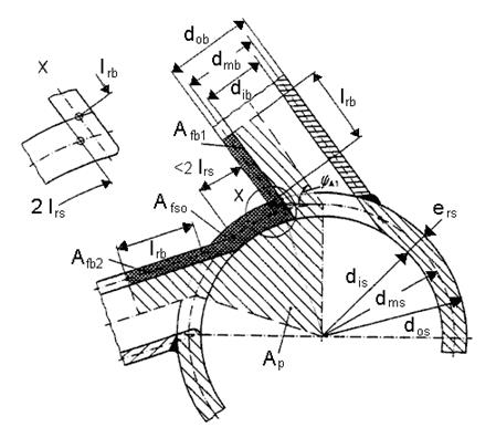
Fig.18: Loading diagram for cylindrical shells with non-radial branch placed circumferentially
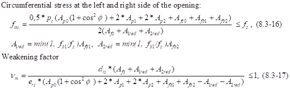
The circumferential stress faφ on the left and right of the opening and the weakening factor are