Introduction
AUZY contains the design of openings and
branches in cylindrical shells according to
section 8 of EN 12952-3.
After having started the program AUZY, a selection screen appears, where the following design types can be selected
· Openings according to sections 8.1 and 8.2
· Single openings with vertical nozzles (8.3)
· Single openings with oblique nozzles and additional reinforcement (8.3)
· Non-radial branch (8.3)
· Y-shaped branch
· Forced integral branch (8.3)
· Adjacent openings and branches (general) (8.3)
A calculation screen appears after selection of the design types. It consists of three regions:
· the input region,
· the result region
· equation region.
Usually, the variables should be entered from up to down and left to right. Dependent variables appear in blue color on the screen and are calculated directly after input of all values. When such a value is overwritten, a dependent variable must be deleted and recalculated. In the standard case all variables can be entered consecutively, until the screen is full and the desired values have been calculated. If there appears no value in an input field, the menu command Option/ask Variable opens a window with all dependent variables. This list contains usually the missing input variable, which is required for the calculation.
The geometrical input variables are illustrated graphically in detailed figures for each design type. In the first four lines of the main window, a help text for the actually active input field is displayed with a short explanation of the corresponding input or output variable.
The geometrical input variables are illustrated graphically in detailed figures for each design type. In the first four lines of the main window, a help text for the actually active input field is displayed with a short explanation of the corresponding input or output variable. An input example is described at the end Example.
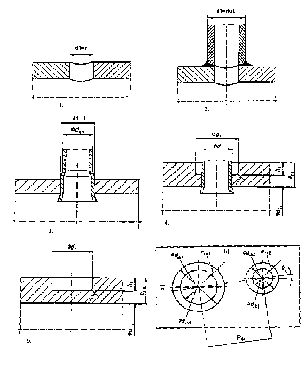
Fig. 1: Variants of the design type 1:
1 Single opening; 2 Attached branch; 3 Roller-expanded seal welded pipe; 4 Roller-expanded pipe with graded hole; 5 Partial drill hole.
Design type 1 comprises single and adjacent openings without support effect of the nozzle according to section 8.1 and 8.2. Five variations of design type 1 are illustrated in Fig.1. Additional detailed drawings and the corresponding equations are comprised in section 8.2.2. If such a variant must be modified afterwards, it is necessary to enter the value 6 first, in order to reset all dependent variables. After recalculation, a new variant can be selected.