ATLAS help
Structure of the ATLAS system
Licensing
Installation
Activation of the software license (*.LIC file)
Parameter study
Simple calculations
Program start / module selection
Basic setting for materials - ‚Project‘ module
Conversion of units
Use definition files / Predefine variables
Expert mode
Variable monitor
Variable dependencies
Complex projects
Connect variables and modules
Set your own values in expert mode
Connecting values (ZUSA module)
The DOKU module
Create revision list
Copy module
Rename and group modules
Split window
Equations
LV QuickSheet
Microsoft Excel Interface
LV Scenario Manager
Saving as database file '*.mdb'
Printing
Selection of the chapters to be printed
Print to
Template/Cover
Load existing company templates
Output format
Insert place holders
Insert logo
Call LV consultant
‘Feezing’ / pay-per-use
Account information
Updates
The engineer cannot be content with using general solutions for special problems.
He needs calculation and simulation procedures which are applicable for almost every case you can think of and which enable you to improve and optimize a solution. That's why we have created the modular LV ATLAS program system. The LV ATLAS program system is being enhanced since 1978 with the help of our customers.
Every process or apparatus can be divided into discrete processes. The LV ATLAS program system is based on these discrete processes which can be put together like units (= modules) of a model kit to describe complex processes. Therefore, every problem based on the extensive series of modules in our LV software can be fully described. By continuously creating new modules our LV team is constantly increasing the versatility of our system.
The mathematical description of the modules is based on a numerical equation solver. This means that users can enter the input data in any order they like. The calculation starts immediately after the input so that the problem is being solved while data entry is continued. This applies both to single modules and combined processes. This procedure enables you to optimize any target variable you like. This results in unlimited possibilities for mathematical examinations of processes. The most important equations are displayed directly on the screen. The values can be entered directly into the formulas.
The ATLAS program system provides more than 400 programs to solve a wide variety of problems. The user can assemble an almost unlimited number of applications.
In refinery processes we deliver solutions in terms of basic engineering. We cover plant engineering and detailed engineering. Due to our long term experience and many projects of different kinds we support our customers in solving their problems. By using software developed by LV and as authorized reseller of WINSIM (USA) in Germany (simulation software Design II) we have reliable calculation opportunities at hand.
The structure of a basic is standardized and adjusted to the complexity of the problem. The processing comprises all operational and process technical measurements and information and leaves no questions in the detailed engineering.
The LV team consists of engineers with long term experience in the fields of process engineering, mechanical engineering and computer science. You always have a competent contact person if you have got questions. We provide individual and company training courses where we teach special design and solving techniques. Seminars and workshop schedules can be found in the internet.
|
Module |
A module is a standalone program dealing with a specific subject, e.g. the GA module 'Heat transfer for flow in tubes' or B1 module 'Cylindrical and spherical shells under internal pressure'. A module comprises all necessary variables for the solution of a partial problem. The according equations are documented.
|
|
Module package |
A module package is a combination of several modules, which exchange information (related variables) dynamically. That means when you enter for example the inlet temperature in a module, this information is transferred to all relevant modules.
|
|
Event |
An event happens if you enter or change a value: An event starts the immediate calculation within a module or complete module package.
|
|
Statement |
A statement can be made for any variable. Important: If a value is not existent, e.g. there is no nozzle in a torispherical head, you need to make a statement! No nozzle => Nozzle diameter = 0. Skipping this input field would mean not to make a statement. The module would try to calculate this value by using other statements. |
The ATLAS system consists of a basic program with more than 400 calculation modules.
The basic program provides general features for solving problems (parameter study, linking, interfaces, Feezing, etc.). The single modules are standalone programs dealing with a specific subject, e.g. the GA module 'Heat transfer for flow in tubes' or B1 module 'Cylindrical and spherical shells under internal pressure'.
All modules have a uniform user interface. The equations are solved by a special equation solver.
While one module deals with a relatively specific subject, any modules can be combined to a project.
The relevant values in several modules can be linked automatically according a defined scheme or manually.
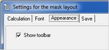
The toolbar can be shown or hidden in the menu
'Options' … Settings / Appearance.
Overview
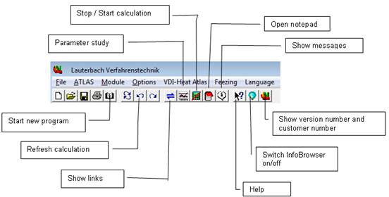
|
|
Function keys |
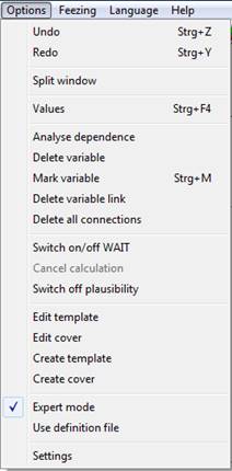
Options' menu |
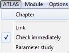
'ATLAS' menu |
|
F1 |
Help |
|
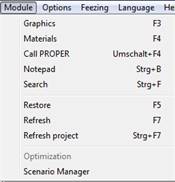
'Module' menu
|
|
F3 |
Display Graphics |
||
|
F4 |
Display material database New material can be selected or documentation of material can be displayed or printed |
||
|
F5 |
Restore module All data are deleted and the module is restarted
|
||
|
F7 |
Refresh module All equations in the module are recomputed
|
||
|
|
|
A frequently used licensing model is the runtime license in a company network (network license). This license permits you to install LV software on as many computers of one LAN as you like. The program is only available for a limited number of computers (depending on the number of purchased network licenses).
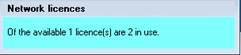
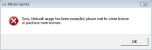
Example: A company with 25 PC work stations purchased 5 licenses. The program has been installed at all 25 computers. It can be used on 5 computers simultaneously. If an additional user wants to use the software the following message appears:
A single user installation is bound to the computer where the software is installed
To receive the unlock code you need to transmit the code from the red field to Lauterbach Verfahrenstechnik GmbH.
By clicking the email button you can start your email client with a ready-to-send email to LV comprising all necessary information.
As soon as you have obtained the unlock code from Lauterbach Verfahrenstechnik GmbH, please enter it into the green field.
Hint: Use the Windows features 'copy' and 'paste' to transmit the code from or to the email text to avoid typing errors.
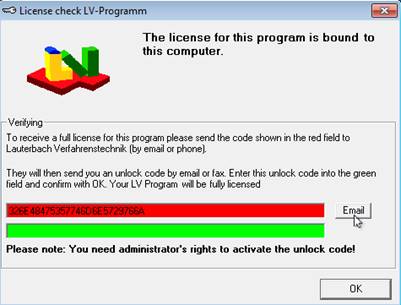
After having entered the code, the program can be used without any limitations. Without an unlock code, the program runs 30 days, but you are always asked to enter an unlock code. After 30 days, the program cannot be used without unlocking it.
Important:
· The code is saved to your PC and is valid for all user logins. You need to have administration rights to install the program (If you can install the program by yourself, you have the necessary administration rights)
· If you install the program to another computer or if you install a new operating system to the same computer, you need to receive a new unlock code.
· If you reinstall the software on the same computer again, you do not need a new unlock code.
With a dongle license you will obtain an additional Hardlock or dongle. The Hardlock is a device to plug in a free USB port. You can install the program on as many computers as you like. To start the program you will need the included Hardlock.
Advantage:
You can purchase one license and use the program either on your laptop or on the office PC, depending on where you have placed the Hardlock.
The Hardlock needs software drivers which might have to be installed.
WINDOWS XP / Vista / Windows 7 / Windows 8 (32bit and 64bit):
Start the USB Hardlock driver installation from the LV program CD:
[CD-drive]:\Support\Hardlock\HASPUserSetup.exe
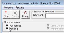
The 'Feezing' technology is a method developed by Lauterbach Verfahrenstechnik GmbH: You can use software when needed by paying a small 'fee'. The software package, which is delivered on a CD, is installed on your computer. Only when you start a program, a short-time internet connection is established to cash up the starting fee. Phone costs are negligible.
Except of information according to cashing up the fees, no data are transferred via internet. Please find detailed information under General
Install the device driver of the card reader from the program CD:
[CD-drive]:\Support\Smartcard\32bit\setup.exe
[CD-drive]:\Support\Smartcard\64bit\setup.exe
Find more information under General
Advantage:
Frequently used software or features can be purchased according to one of the license models above. Programs you need only occasionally can be used by 'feezing'.
To be able to work with LV programs optimally, we recommend:
· Windows 7 / Windows 8 and 8.1 / Windows 10 (32bit or 64 bit)
· Office System compatible, e.g. Microsoft Office or OpenOffice
We highly recommend deactivating all anti virus software before installing and re-activating it after installation.
You need administration rights to install the software. The LV programs can be installed as single user or network version.
With a single user version, all program components are installed on the work station.
With a network version, the main program components are installed on a network server. Only a couple of system files have to be installed on the different work stations.
Advantage: When you are updating the program, only the components on the server have to be updated.
· Insert the CD into the CD ROM drive
· Select 'Run' in the 'Start' menu
· Choose the CD ROM drive with the 'browse' button.
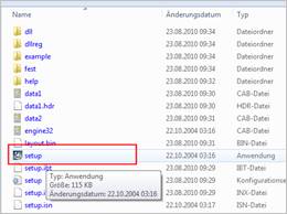
· Switch to the 'LV' directory and select the setup.exe. If you have purchased several program packages, please select the setup.exe in the according sub directory (stress, heat, etc.)
· Execute the 'setup.exe' with a double click
The installation wizard guides you through the rest of the installation procedure. Sometimes the computer has to be restarted after the installation.
We recommend a complete installation. Tick all boxes.
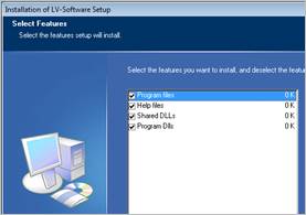
For installation administration rights are required.
Please read carefully to avoid unnecessary questions!
1. To enable further work stations to work with the software installed on the network server, an installation on these work stations is necessary. It is sufficient to install the libraries (DLLs). If you perform a complete installation, the files already installed on the server are overwritten.
2. To ensure that all program components can be found on the server, you need to state the server directory where the program is installed, when installing on a workstation.
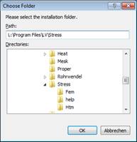
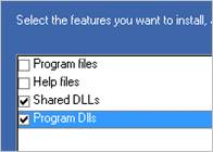
You can specify a network path (UNC) or a mapped drive.
Hint for the single workstations
1. It is sufficient to install the libraries (DLLs) on the work stations
Additionally the unlock key must be activated on each work station, see: Activating the license:
The type of the license (floating network, single user with unlock number or hard lock installation) is saved in a license file, (LIC file), which you receive by email.
The license file has the same name as the program package it is made for (e.g. ATLAS.lic).
The license file contains the following information:
1. Unlock information of purchased modules (displayed in black in the treeview of the module selection)
2. Unlock information of all modules (alphabetical listing of modules) you can use, by paying a small fee (FEEZING) or you can unlock at a later point of time by purchasing them (displayed in light gray).
3. The type of licensing (single user, network, hard lock)
4. Your client number
You can activate the license manually or automatically.
Automatically: Save the license file in the program directory of the installed program
(By default: C:\Program Files (x86)\LV\“NameOfPackage“)
When you start the program, the program searches for a valid license file in the program directory and asks if it shall use this license. Confirm with ‘yes’ and the license file is read and the license is activated.
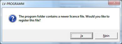
A restart oft he program is required!
Manually:
Select „Help / Activate license‘, select a valid license file and confirm with OK.
Or: „Help – About“ - „ Activate the license “
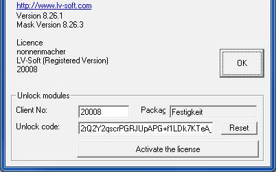
After having activated the license, you can archive your license file anywhere.
Open the Windows 'Start' menu and start the program by selecting 'Programs' / 'Atlas' / 'ATLAS'.
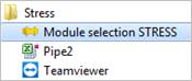
Start the strength calculation software by 'Programs' / 'Stress' / 'STRESS'.
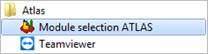
Open the Windows 'Start' menu and start the program by selecting 'Programs' / 'Atlas' / 'ATLAS'.
Start the strength calculation software by 'Programs' / 'Stress' / 'STRESS'.
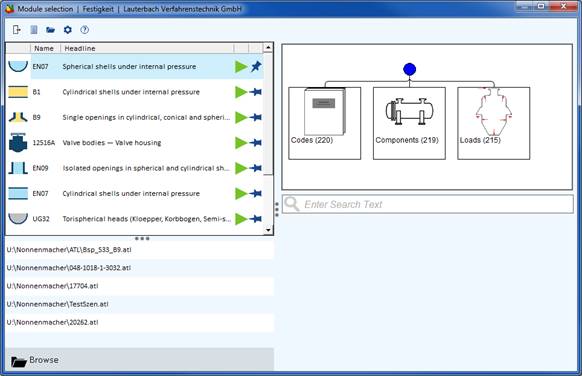
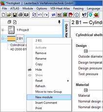
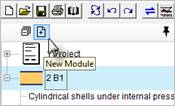
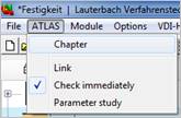
When you already have started a module, you can call up the module selection via “Atlas/Chapter” or by right-clicking the symbol and selecting “New module” or you can use the plus button in the project overview.
You can find the correct module for solving your problem in many ways.
As a rule, the first hit is the best hit.
Start the module by double-click or by
using the green start button. 
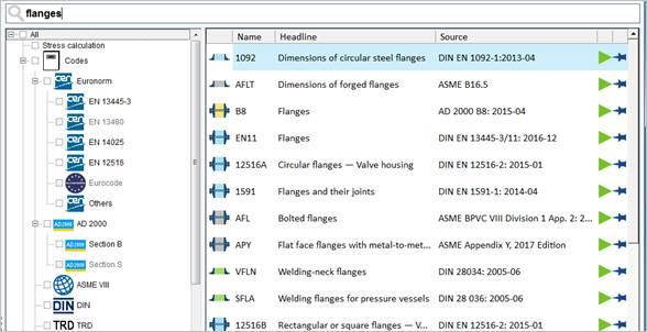
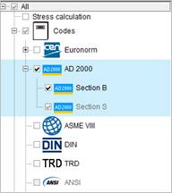
Using the filtering options, you can refine your search.
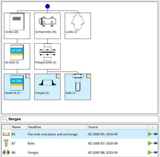
Find the module for your task by selecting the according categories and symbols.
At first program start of the strength calculation software, you have to specify the delivery standards for your materials.
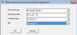
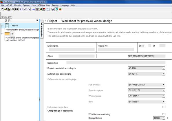
When you start a calculation module in the strength calculation software, the Project module is started automatically. The delivery standards are already entered in this module, but you can change them individually for every project.
Enter the regulation you want to use for the calculation and the regulation for the material definition.
E.g. Calculation according AD 2000, but materials according DIN EN 13445-3
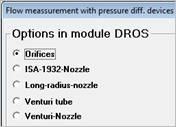
Many modules require a selection of one or more basic options before you can enter design values.
The DROS module (Flow measurement with pressure difference devices according to EN-ISO 5167-1/A.) for example needs to know if you want to calculate orifices or a Venturi nozzle.
Most modules have a Quick-Navigation Menu, which flies out when you click on the Quick Navigation Bar.
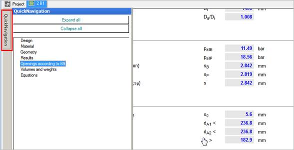
Here you can jump directly to the specified section in the input mask and you can easily expand or collapse all sections of the mask.
A right click on the navigation bar or a left click on any spot of the mask hides the navigation menu.
Fundamentals
Due to the modular structure of the LV ATLAS there is a unified user interface in every module.
There are no specific input values and defined output values.
Every value on the mask can be input value. After each input the program checks if it can calculate other values by using the last input data.
To distinguish between the values entered values are displayed in black and calculated values are displayed in blue.
Given is a rectangle with width a and length b.

As soon as you have entered both values and left the input field, the area of the rectangle is calculated.

If you change one of your input values a or b at any location on the input mask, the new value of the area is calculated immediately.
If you overwrite the result of a calculation, in this case the area of the rectangle, a list with all dependent variables is displayed. In this list you can select which value you want to define as a new target value.
Example: Area is given, and the width is our new target value:

The unique Equation Solver by Lauterbach Verfahrenstechnik GmbH is an essential part of the LV ATLAS program system
At first sight, the operating procedure of the equation solver might be unfamiliar. However it provides the user with a state-of-the-art tool for designing and optimizing all kinds of process engineering apparatuses and equipment.
You can also enter ranges of values directly into the input fields. Format must be 'NUMBER to NUMBER'
(Ex: 1 to 4).
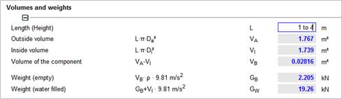
The individual values can be changed by using the slide control with the left and right arrow keys. All dependent values are calculated instantly.
Input values in the ATLAS program system can be taken from a database of values for several physical units. The database can be called up directly from the input mask.
In many modules, the geometrical data can be entered in the graphics directly on the input mask. The graphic can be printed for documentation. This feature serves also as input control as predefined values are displayed in the graphic.
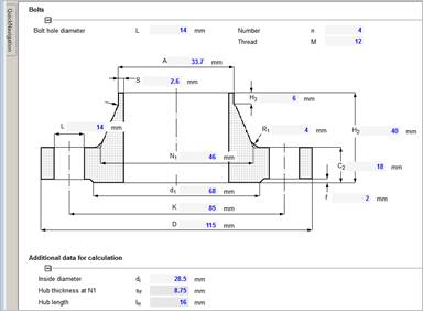
With this feature, the LV modules fulfil the requirements of the EN 13445 for the documentation of pressure vessel calculations.
The conversion of units of a value is activated by
· Single mouse-click on the unit on the input mask
· Key combination SHIFT - Cursor Up / Down
· Right mouse-click menu 'Conversion of units' on an input field
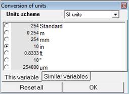
Activate the conversion of units as described before and enter the value in your desired unit. The conversion is done automatically. The displayed unit on the mask does not change.
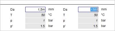
Use the option buttons to change the unit that is displayed on the input mask.
The checked button determines the unit in which this variable is always displayed.
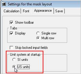
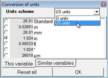
Via 'Options / Settings / Appearance you can set the unit system. Changes require a restart of the program.
Frequently used variables may be predefined at module start.
Save the module as definition file after having entered the variable.
Next time the module is started the variables are preallocated with the values you have saved.
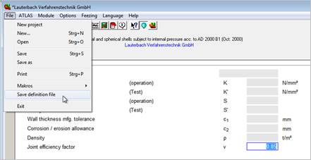
Please note:
‚Use definition file’ must be activated.
1. Input values (displayed in black) may be changed at any time. All equations related directly or indirectly with this value are calculated at once.
2. Calculated values (displayed in blue) may be overwritten, but then the equation system is over-determined. If this equation consists of only two variables, the system calculates the other and treats the changed value as input value.
If more than two variables determine the equation, the user has to decide which former input value shall be calculated from now on. A new window
'Clear variable' is opening.
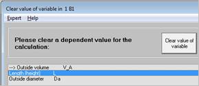
In this window all values which are related by equations and rules to the last input value.
The value which has to be cleared for calculation is selected with the mouse (double click) or with the cursor (up and down key plus ENTER)
After program installation the expert mode is inactive by default. In 'standard mode' only standard input fields are displayed. Calculated values or values from a database cannot be changed.
Advantage of Standard Mode: As a newcomer user you are not able to make many mistakes. The equation system is always defined.
|
Advantage of Expert Mode: You can overwrite calculated variables with an input value to enable the program system to compute backwards to a value which was an input value before. By selecting 'Options' / 'Settings' / Calculation you can activate or deactivate the 'expert mode' or single components. |
The program calculates all equations after the input of a new value. If you want to change multiple values without the program calculating immediately, use the calculator icon to stop the calculation for the moment and resume it when you are ready.
Stop calculation

Resume calculation
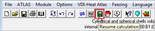
A complete new calculation of all values of the module can be started by pressing the [F7] function key or selecting 'Module' / Refresh' or [CTRL-F7] or 'Module' / Refresh project' to refresh the whole project.
With the <ESC> key you can cancel a running calculation. As there are my iteration steps to cancel you should hold the escape key down until the program lets you enter a new value.
If there is additional information available on a specific variable, a question mark is shown

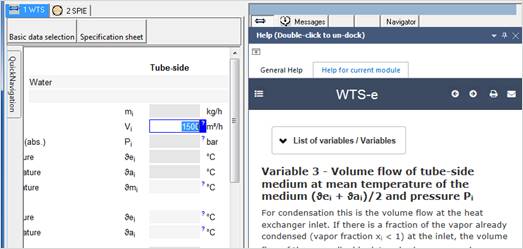
When clicking on the question mark, the additional information is displayed in the Info Browser.
Program messages are classified in two categories. Critical messages and hints
By default these messages are displayed as a popup window in the program and must be closed individually with a mouse click.
To avoid a disturbance of your work flow, you suppress multiple messages.
Go to Options / Settings/ calculation and tick the entry 'Suppress multiple messages'
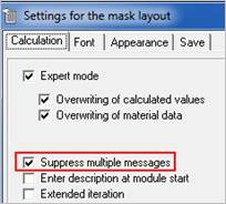
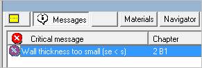
New messages are then not shown multiple times as pop-up, but only once and then summarized in the message browser.
Next to the input mask you may display an area with additional program information or the help system.
The additional information is variable-specific. Program messages and the variable monitor are shown in this area. The blue light bulb disables or enables the InfoBrowser.
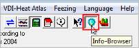
The help system is a true online help, shown in the InfoBrowser. An active Internet connection is required!
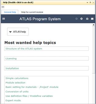
The help system is fully responsive, i.e. it adjusts completely to the sitze of the InfoBrowser window. By double-click you can undock the help sytem from the program and display it on another screen for example. The next double-click docks it into the program again.
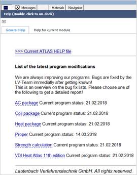
General Help
The general program help and the latest bug fixes are shown.
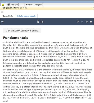
Help for current module
This item shows the help files for the current module. When switching to another module, the help file does automatically change as well, if there is a help file availabele. The help system includes additional information or hyperlinks to other pages or references to PDF files. PDF files are shown in the InfoBrowser if the correct plugin or the Acrobat reader from Adobe is installed.
By clicking with the right mouse button on a variable input field you will see a context menu.
By selecting ‘Properties’ the variable properties are displayed.
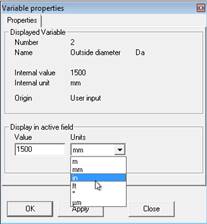
In this mask you can also change the displayed unit.
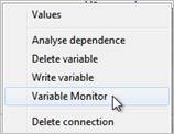
While designing an apparatus you can now observe changes in a variable with the 'Variable Monitor'. (Right mouse click on the variable).
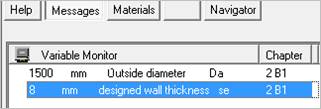
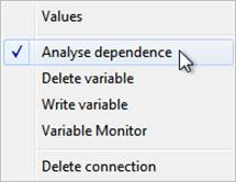
Which variables are mathematically related?
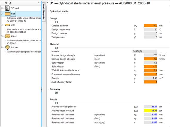
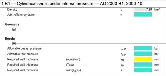
By using the option ‘Analyse dependence', all variables, which are mathematically dependent upon each other are highlighted in different colours.
|
Turquoise |
Influencing variables |
|
|
|
Orange |
Depending variables |
|
|
|
Yellow |
Examined variable |
|



Many modules have their own help file which you can find in the 'Help' menu under 'Help for...'.
Help for the general features of the ATLAS program system you can find under 'Help / Help topics'.
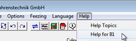
An Internet connection is required!
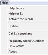
Call LV consultant
If an LV user has complex questions concerning a calculation which are difficult to describe on the phone he can call an LV consultant. An engineer dealing with your subject will connect to your PC via TeamViewer.
A PC to PC connection will almost always result in a solution presented by LV.
Update... 24 hours
Within a service contract you can update your software by pressing one single button. You can decide when or if you want to be reminded to update your software. Before starting the download the available version number is displayed.
Acivate the license
Reading the license file (.lic) to unlock the program (see )
About
Here you will find information about your version number mask version number and customer number.
The individual calculation modules of the LV ATLAS program system cover only a limited field of application each. With the B3 module for example you can design the head of a vessel. With the LDA module you can calculate the pressure drop in tubes.
The engineering problems comprise many partial aspects. A complete vessel consists of head, shell, flanges, nozzles, gaskets, etc.
To solve these complex problems, many modules can be summarized to a project. Start one module for each partial problem, e.g., another B1, B9, etc. The modules can be linked with each other, i.e. if you change for example the vessel diameter in one module the diameter is transferred to all other relevant modules. You can copy modules. You don't have to enter all data for similar parts again.
Find the basic settings for the material delivery regulations in the ‘Project’ module. See Basic setting for materials - ‚Project‘ module
You can summarize the modules to groups and you can name these groups to keep complex projects clear and understandable.
You can link the variables of different modules of a project. When changing the value of a variable the value of the linked variable is updated immediately. Additionally the module in which the linked variable is located is recomputed.
Every module requires several input data before the calculation is performed. With LV software you need to enter these data only once. You can connect the variables of different modules. / B1 to B9.
Drag the tab from B1 to the input mask of B9. You will see a connection cursor. Only suitable units are automatically connected.
Let go the mouse button and drop the values into the B9 module. The modules are now connected.
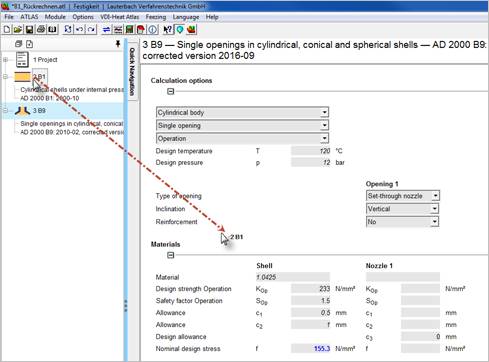
If you now change the values in one module, the values are automatically updated in the other module.
First highlight the 'link source' by jumping to the input field of the variable. Then open the popup menu with a right mouse click. Select 'Write variable'.
You can also use the key combination <Ctrl-M> which is faster.
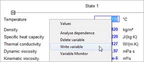
Best way is to write all relevant variables, for example the properties density, heat capacity, viscosity, thermal conductivity in a properties module.
Then switch to the target module, highlight the target variable and right click again
In the menu item 'Link with' you will find all source variables with a matching unit. If there are more than five suitable 'source variables'' and the desired source variable is not displayed, you can call up a complete list of all links.
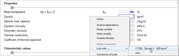
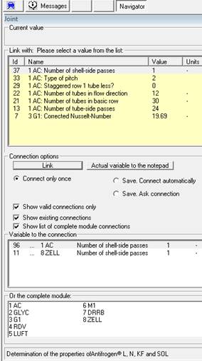
This list shows only links with matching units for the activated variable.
If the filter is deselected all active links and link partners are shown.
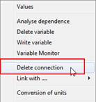
A link can be deleted by selecting 'Delete connection' in the right mouse click menu.
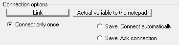
You may connect variables only once, always automatically or on request.
Sometimes you need to use a value that is differing from the calculated value. You can replace the calculated value without interfering with other values:
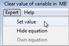
Select 'Set value' in the 'Expert' menu.
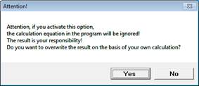
A warning message is displayed and you are asked to give a reason for the differing value:
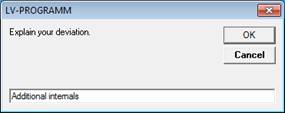
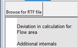
The reason is documented in the DOKU module. The differing value is displayed in red on the input mask.

The ZUSA module enables you to summarize text and values in your project.
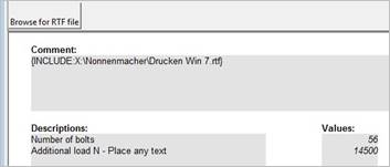
With ‚Write variable’ (right mouse click) you can mark all relevant variables for the summary.
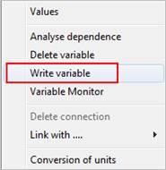
Switch to the ZUSA module, activate the target variable and press the right mouse button.
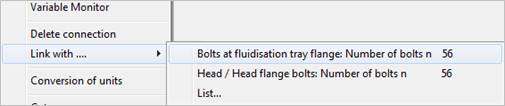
By „Link with...“ all source variables are offered.
With a double-click the values are linked.
When you now change a value in a module all linked values are updated automatically. Your documentation is always up-to-date.
The DOKU module allows you to integrate as many additional text as you want into your documentation for later printing.
Complete RTF or DOCX files can be included and revision lists can be built.
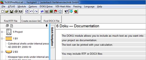
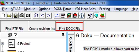
In the DOKU module you can build an automatic revision list.
Load a file to revise by pressing the Create revision list button’. The date of the file will be displayed as headline in the DOKU module.
Then make your revisions and save the file under a different file name (e.g. Rev. 2).
Press the button again and open the first file (Rev. 1).
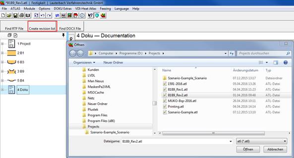
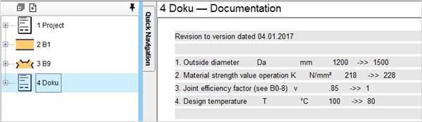
The program will automatically compare the changes and write them into the DOKU module.
Changes have been made in the B1 module.
For example: The outside diameter was changed from 1500 mm to 1200 mm.
To get a better overview or to find details, right-click on the input mask and select ‚Zoom’. The slide control lets you zoom in or out. The value next to the slide control is the font size.
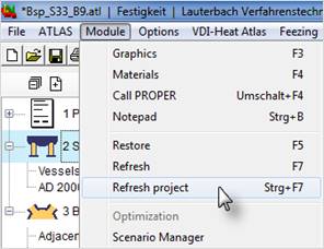
All modules of a project are re-calculated and the values are updated. According to the number of modules in the project this may take a while.
Right click on the module symbol – Reset
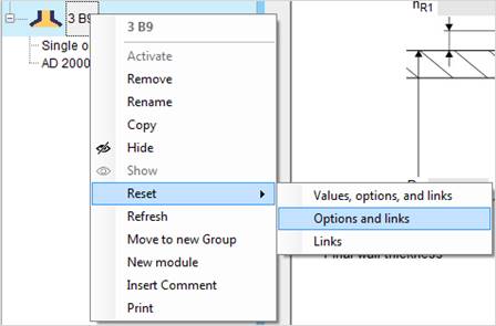
Values, options and links
Resets the module and you can select a new construction type and enter new values.
Options and links
Resets the module and you can select a new construction type. The entered values keep untouched if possible.
Links
Deletes all existing links oft he selected module.
Right click on module symbol. The module is hidden in the project but does still take part in the calculation if there are connections to other modules. Hidden modules can also be printed.
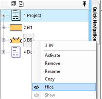
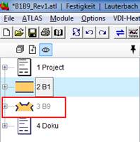
>> Hidden modules are not displayed by default. You can show them by selecting the Show Hidden modules button. They are displayed in light grey.
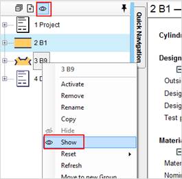
To show the module again, right click on the symbol and select ‘Show’. The button Show hidden modules must be activated!
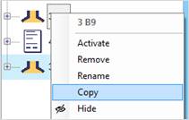
Often it is very helpful if you can calculate a variant of your calculation with one or more differing values. You can copy the complete module with your calculation with a right mouse click.
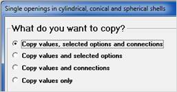
If you copy the values only, the new module asks for the basic data. The values in the copied module are not compared with the values of the other modules in the project.
If you copy also the connections, the values are treated as in the source module. E.g. the same diameter in all modules, provided that the value has been linked within all modules.
If you copy also the type, the copied module is exactly the same as the original module. You may then change for example a tube length while all other values are identical to the values of the original module.
The result is a copy of the module:
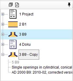
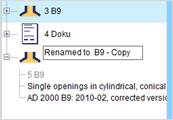
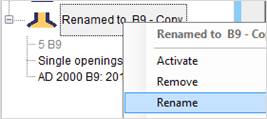
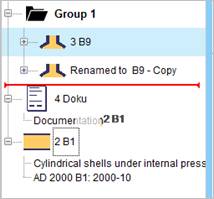
Modules or groups can be renamed. Remanimg is done the exact way as in the Windows Explorer. Click on the module name or right-click the module symbol and ‘rename’ to enter the edit mode.
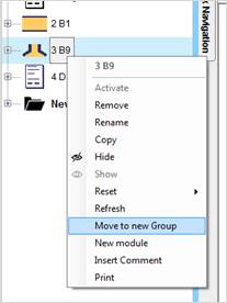
Modules can be summarized in groups. Select Move to new group' with a right mouse click
Name the group. The name can be changed at any time.
Add a module to a group by drag and drop. A red line shows the position , where the module will be dropped.
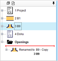
Creating a group within a group (subgroups) is not possible!
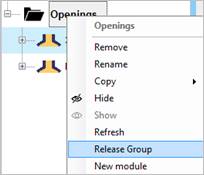
Release a group with a right-click on the group icon and “Release group”. The modules are then available as individual modules again.
The order of the modules can be changed by drag and drop as well. Whole groups can be moved. A red line shows the position , where the module will be dropped
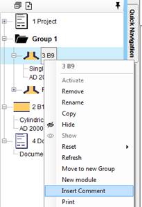
You can add a comment to every LV module. Right click the symbol and ‘Insert comment’
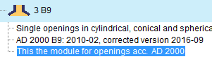
The comment is not printable!
A parameter study can be performed to visualize the relations between variables, to find minimum and maximum values or to create tables with several rows of values.
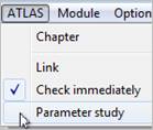
Start the parameter study with the button 'Parameter study' in the toolbar.
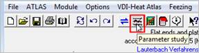
Or ‘ATLAS – Parameter study’
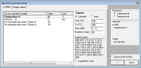
Select the loop variable and the support values for the parameter study in the dialog. Set interval boundaries, distance and/or number of support values to receive steady intervals. The program determines e.g. the interval if you enter the number of support values or the upper bound. By selecting a logarithmic scaling, the interval of the support values increases exponentially.
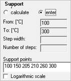
You can also enter discrete values. The values must be separated by a blank.
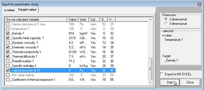
Determine the target values, i.e. values which are calculated at the support points. Just tick the variables you want to determine
Values displayed in light grey have not been calculated by the module and may therefore probably not be related to the loop variable. Such values may be 'imported' from other modules, though. Then they may be related via this connection with the loop variable.
Results can be exported to MS Excel immediately.
The 'Start' button starts the calculation.
Each target variable is displayed in the results dialog with its own tab.
The results can be displayed graphically by opening the 'Graphics' menu and selecting the desired kind of graphics.
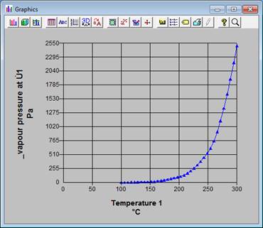
The graphics program „Graphics Server“ used by the ATLAS program system provides multiple features for displaying the diagrams or exporting the graphics to e.g.. bmp, gif or tif files. The features of the 'Graphics server' are explained in its own manual.
You can start a two dimensional parameter study directly from the target variable on the input mask. Enter the parameter values in the following way:
Example:Enter 1,1.1…2 for the total mass flow in kg/s
It means:
1 = starting value
1.1= second value
IMPORTANT:
The dot (.) is the decimal separator.
This leads to the size of the steps. In this case 0.1. The sign "…" means go on with all further steps until the end value.
2 is the end value
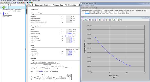
A parameter study is performed automatically for all dependent values.
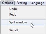
Similar to the MS Office programs you can split the window to get a better overview.
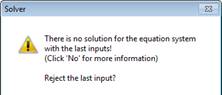
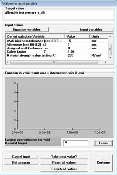
If you change some calculated values (e.g. heat transfer coefficient) and after that clear a variable (e.g. geometrical values) the iteration routines might not be able to find a solution. We recommend to reject the last input with Yes .
In the other case a window for the analysis of the insolvability is displayed.
Now you have the possibility to continue the iteration, take the best value or to clear a new variable with continue and resume the calculation.
With Focus the area of a possible solution is enlarged.
In expert mode only:
Search all values
All mathematical solutions which might be physically impossible are searched as well.
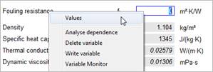
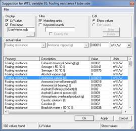
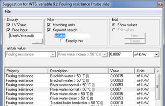
In the proposition list only units matching the unit of the input field are displayed by default. The main criterion is the unit. For the unit 'mm' for example the units 'm' and 'inch' are displayed as well.
Filtering by unit
If you want to see all values, deselect the box 'Matching units'.
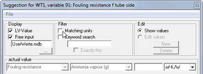
Keyword search
You can limit the number of selected values by entering a keyword:
You may look for example for fouling factors of any kind of water
A more detailed search can be performed by activating the check box 'Exactly this'. Only values are displayed matching the keyword perfectly.
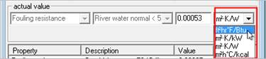
The unit of the displayed value can be changed. The value is displayed accordingly
Sorting by columns
By clicking on the head of a column, the table is sorted by this column. With a second click you can switch between sorting in ascending or descending order.
Equations where all variables are known are presented in black. Equations shown in grey have missing values, which are either not entered or not calculated, yet.
A mouse click on the equations shows which variables are used in this equation.
With a further mouse-click on the variable of the list you have access to all variable options you have with a right-click on an input field. This is e.g. the way to connect variables of an equation with MS Excel.
With the new LV QuickSheet you will achieve your goal even faster.
You want to solve a problem for which you need several LV modules? Then the new LV QuickSheet gives you the option of managing all module combinations created in a project using an independent input mask.
This means that you can control all previously entered input values clearly on one screen without having to switch between the modules/chapters. All required input fields of the corresponding modules are clearly displayed and you can enter new values for each size or have certain values of your previous input entered automatically. In addition, all your previously created connections of variables that you created in the modules before creating the QuickSheet are retained.
This allows a complex task to be processed conveniently via a single input mask.
The QuickSheet is a simplified input mask reduced to the essentials, without any redundant details.
We offer you QuickSheets designed for various tasks, with which you achieve a significant added value compared to a conventional calculation.
To create a new QuickSheet, first set up all your required modules as usual. Enter all the required variables and select all the settings required for the calculation. As usual, you can link variables in the modules that are to represent the same size.
Now select the option "Create Quick Sheet" on the "File" tab. An overview window of the QuickSheet will appear. Here you can find the values you entered with the assignment to the chapter in which the value is used.
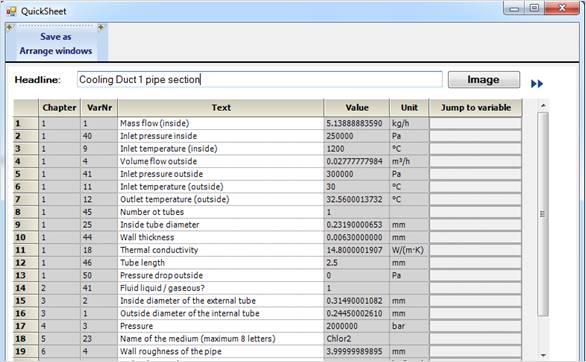
Create QuickSheet Overview Window
You can select the following options from the command line of the QuickSheet overview:
|
Save as |
Saving is always associated with the mandatory specification of the storage location in order to avoid accidentally overwriting an existing QuickSheet with the same name. The default save name corresponds to the name of your project / saved .atl file. |
|
Arrange windows |
Arranges the windows on the screens side by side. |
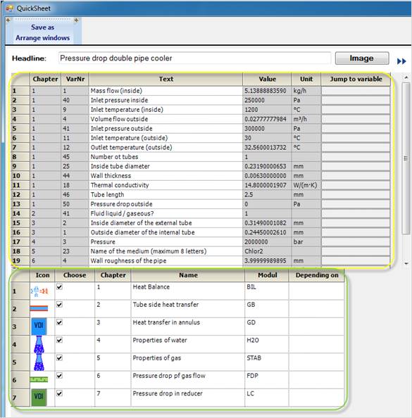
Create QuickSheet
In the field behind the description "Heading" you can assign your own heading for your QuickSheet.
Note: This is not the savename of your QuickSheet.
By selecting the "Image"
option, you can assign your QuickSheet your own logo, which will later be displayed
in the treeview like the symbols/logos of the modules.
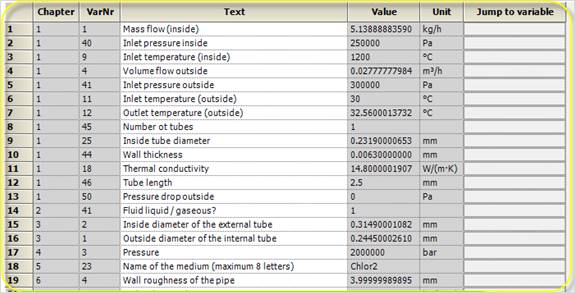
The column headings of the yellow framed table stand for :
|
Chapter |
Program internal numbering of the module you created |
|
VarNr |
Module-internal numbering of variables in a specific module |
|
Text |
Description of the variables, according to the designation in the module. This text can be changed at any time. |
|
Value |
Value of the input variable |
|
Unit |
Unit of the input variable |
|
Jump to variable |
After clicking on the field, the view jumps to the corresponding variable in the corresponding module mask. |
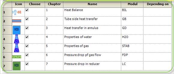
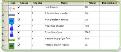
In the table framed in green, you now have the following options:
|
Icon |
Internal program logo of the used module. This cannot be changed. |
|
Select |
Here you can select the modules that you want to have created in your QuickSheet. A check mark activates the corresponding module for creating the QuickSheet. |
|
Chapter |
Program internal numbering of the module you created. This cannot be changed. |
|
Name |
Description of the module, according to the designation in the program. This text can be changed at any time. |
|
Module |
Program internal module name, according to the name in the program. This text can be changed at any time. |
|
Depending on |
Here you can enter dependencies between the modules for a better overview. This has no effect on the calculation sequence and only serves your overview. |
To load a new QuickSheet and add it to
your existing project, select the "Chapter" option in the
"Atlas" tab or select the Add icon  above
the TreeView in the "Project Overview" tab. Opening a QuickSheet is
only possible from within the program, not from Windows Explorer.
above
the TreeView in the "Project Overview" tab. Opening a QuickSheet is
only possible from within the program, not from Windows Explorer.
If you select the Create New Project
icon  or select the "New..."
option in the "File" tab, a new empty project is created into
which you can then load your QuickSheet. Your existing project can also be
saved beforehand.
or select the "New..."
option in the "File" tab, a new empty project is created into
which you can then load your QuickSheet. Your existing project can also be
saved beforehand.
In the module selection that appears, select Quick Sheet from the upper command line. Now you can load your existing QuickSheet
Now all modules contained in the QuickSheet are inserted into your existing project if necessary and afterwards the QuickSheet mask opens, which can look like this for example:
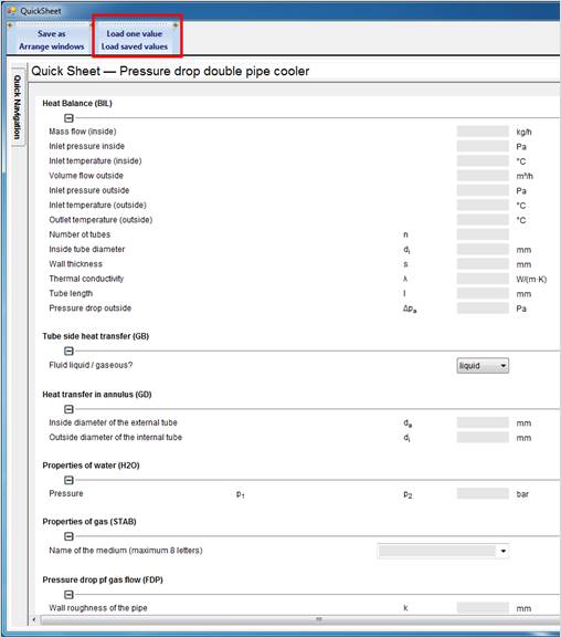
QuickSheet Input Mask
This is an independent mask which displays all input values of the modules you have selected. The individual sections have the names of the previously entered names in the columns with the column headings "Name" and "Module" of the QuickSheet overview.
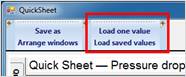
The two new options "Load a value" and "Load stored values", framed in red, have been added to the command line.
You have the following options for defining input values:
1. You enter a value directly in the corresponding field of a variable yourself.
2. automatically enter all values as you entered them when you created the QuickSheet.. Loading Saved Values
3. ou automatically enter individual values as you entered them when you created the QuickSheet. Load a value
Select a variable field and click on "Load a value". The value specified in the corresponding .atl file is transferred to the active variable field.
All values are also entered on the module mask after being entered on the QuickSheet mask. Depending on the order in which you enter the values, this can lead to message windows appearing, which you have to close to be able to continue the input.
You can add variables to the QuickSheet template at a later point of time.
Use Drag & Drop to drag an existing variable field from a module mask to the QuickSheet mask. The corresponding size appears in the corresponding section of the module.
If possible, do not use values calculated by the program, otherwise other sizes may have to be released. This also results in non-solvable systems of equations.
You can change the texts and symbols of the variables on the QuickSheet screen at any time by right-clicking on a text and selecting Edit Text.
You can now enter any text. This has no effect on the names of the variables in the linked modules.
It only serves to give you freedom of design on the QuickSheet screen.
Especially in process engineering it is often necessary to perform calculations iteratively.
A starting value for different sizes is required so that the first iteration step can be carried out. Start values can be entered in the module mask by placing an "s" after the numerical value when entering the value, which stands for "estimated value". Thus the system recognizes these values as changeable and varies these with each iteration. These values are displayed in green on the module mask.

In order for the calculation to run correctly, it is necessary to define these initial values first. Values previously entered as estimated values are therefore listed first on the QuickSheet screen and do not appear in the chapters below.
You also have the option of dragging and dropping variable fields from the module mask to the QuickSheet overview to define them as start values.
Now the corresponding variable will appear first on the QuickSheet under the newly created section heading "Initial values".
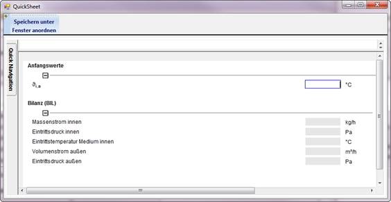
QuickSheet mask with "Initial values" section
A Microsoft Office Package with Excel at least MS Office 2010 must be installed.
Additionally an LV Program package with unlocked programs is required.
Start for example the WTS program and enter your values or load an existing ATL file.
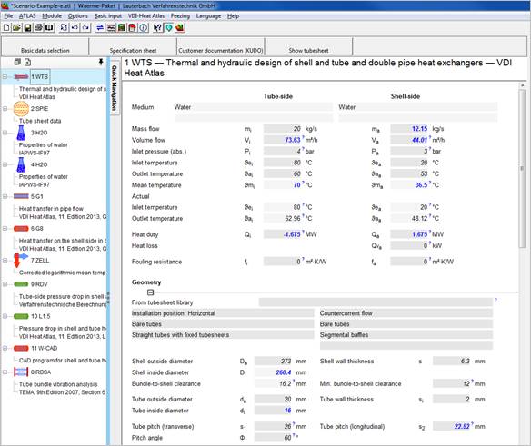
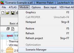
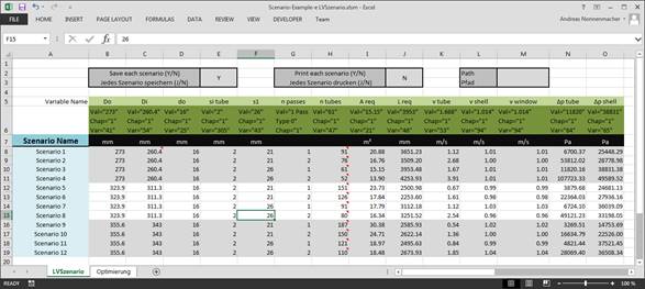
The EXCEL scenario file opens by Module – Scenario Manager (File name LVSzenario.xlsm). If you have not saved your calculation, the program will now remind you to do so.
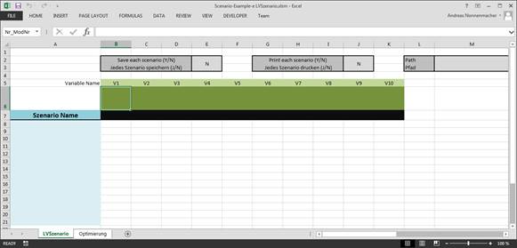
1. First enter a scenario name
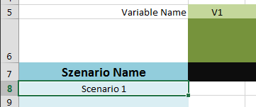
2. Enter the variable description
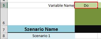
3. Transfer the variable number by Drag&Drop. Drag the variable from the LV program to the EXCEL input filed.
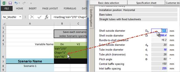
It means:
Val=“237“ Current value = 273 (not used in scenario)
Chap=“1“ Chapter = 1
Var=“41“ Variable number = 41
4. Enter the value of this variable:
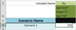
5. Enter the desired output unit. If you leave this field blank, the internal program unit is used and entered.
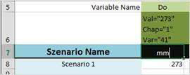
Proceed like that with all variables you want to vary. Create as many scenarios and variants as you want and save the file as EXCEL file (.xlsx).
Start the ‘Scenario Manager’ in the ‘Module’ menu
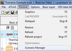
The Excel file is now filled with results and the according results files (ATL, PDF, RTF, as selected) are written to the output path.
Select ‚Y‘ (Yes) for this option and each and every scenario is save das ATL file. A folder is created with all scenario files. The folder is named like the ATL file the scenario is based on.

If you select this option with ‚Y‘, each scenario is printed as a single file.
Set the appearance of the printout and the way of printing (PDF, RTF or printer) once. Then all files are printed the same way automatically.
The Output formats are described in the manual in detail.
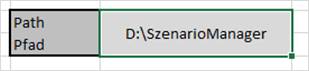
Set the path where all files are saved by default.
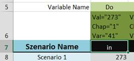
The units are automatically transferred from the LV program to EXCEL. If you want to change the unit, enter the desired unit and start the scenario manager again by „module – Scenario Manager“.
If you want to calculate only specific scenarios, simply highlight these scenarios in the EXCEL file and start the scenario manager again. Only the highlighted scenarios are calculated
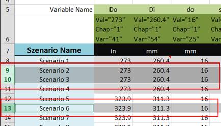
If you want to skip scenarios, enter SKIP as scenario name.
The run of the scenario manager ends when it comes to an empty scenario name field.
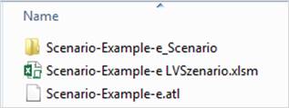
For every ATL file there is a coupled Excel Scenario Name.
Example:
You work with the file „D:\Projects\Scenario-Example.atl“. Then the coupled scenario file is named: „D:\Projects\Scenario-Example LVSzenario.xlsm“.
When you start the scenario manager the program checks if the coupled EXCEL file exists. If it doesn’t, the template file is copied to the folder and an empty scenario file is started. If it does, the scenarios are run.
This all happens automatically and is only to be considered in the following cases:
If you want to move, copy or rename the ATL file, you also have to move, copy or rename the EXCEL files.
If you want to discard all scenarios, you only have to delete the according EXCEL file.
LV-Software – MS Office from Version 2010 on with MS EXCEL installed
Start any LV module.
Start EXCEL and open a new worksheet or load an existing worksheet.
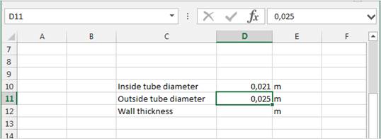
Select the EXCEL cell, which shall receive the data.
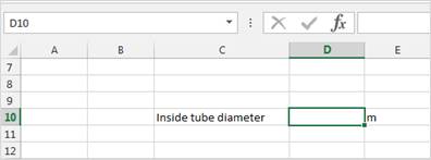
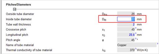
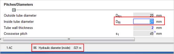
Go to the LV input field that contains the data you want to transfer to EXCEL.
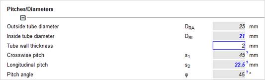
Right-click on the field: ‘Excel – to current Excel cell’
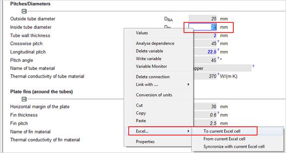
The data from the LV program are transferred to Excel.
>> Changing the value in the LV program, changes the data in the Excel worksheet.
IMPORTANT:
All values are transferred with the internal standard unit (here: m) and not wit the unit you have set in the input mask (here mm)!
You can see the internal standard unit in the program footer, when highlighting the field. In our example [m] instead of [mm].
Select the EXCEL cell containing the data to transfer to LV.
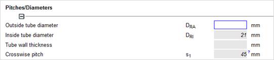
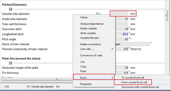
Mark the input field in the LV program, which shall receive the data.
Right-click on this field ‘Excel – from current Excel cell
Data from Excel are transferred to the LV program.
>> Changing the value in Excel updates the value in the LV program.
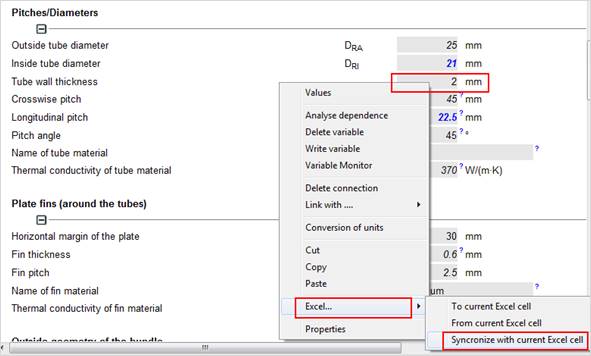
Select the Excel cell with the data to be synchronized.
Select the input field in the LV program where you want to synchronize the data with EXCEL.
Right-click and select ‘Excel – Sync. with current Excel cell‘
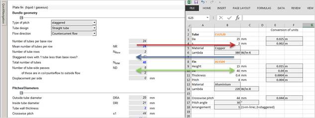
Data are synchronized between Excel and LV.
>> You can change the values either in the LV program or in MS Excel.

Save the Excel file to any arbitraty location. The path to the Excel file is saved in the ATL file. When you open the ATL file, the saved Excel file (.xlsx) is opened as well.
ATTENTION:
If the Excel file is moved to another location, deleted or renamed, the LV program will not be able to open the Excel file and will display a message.
If you move the Excel file tot he location where the LV program expects the file to be, or restore the original name, the LV program will find the Excel file and set the connections..
Addition
LV Variables can be connected with Excel cells. Only one link from or to Excel is allowed per input field.
With the additional module "LV Excel Templates" it is possible to save the connections in a template file and use it in the according module if required.
· You have construction tables in MS EXCEL for the geometrical data of your components.
· You have physical properties of e.g a specific refrigerant in MS EXCEL.
· You have a calculation sheet in EXCEL, where you want to enter values from teh LV calculation.
Avoid typing mismatch. When you are changing values the connected components are automatically updated.
This part is the same as before when connecting Excel cells with LV fields: Starting an LV module, opening an Excel sheet and connecting variables ( s. Operation in general)
Select the following menu item „Excel -> Convert current workbook to template“. Now you have to enter a name for the template.

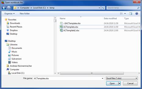
Open the module you want to use with the template. Then select Excel -> Load template.
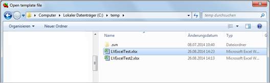
Select the saved template. This template will now be copied and connected tot he LV module. Select a location to save this excel file. Then you can continue working as usual.
To separate the Excel file – LV coupling, select: ‘Excel - Disconnect workbook ‘
All started modules including their alternatives and comments are saved with the menu item "Save" in the "File" menu. The dialog 'Save file' is displayed:
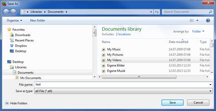
Backup files get the extension "ATL".
Calculations within the ATLAS program system can be saved as MS Access database file. This file format saves the data as tables. The meaning is specified in the column and row names. This gives access on the ATLAS calculation.
Other software is able to read and change this data.
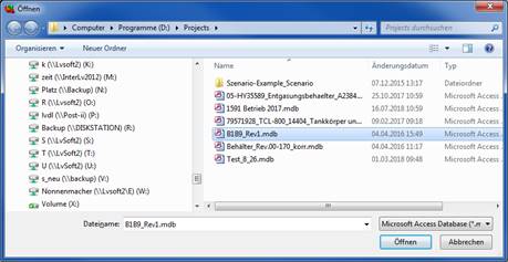
The database format enables you to integrate saved calculations into the present project. Save standard solutions or frequently occurring calculations as database.
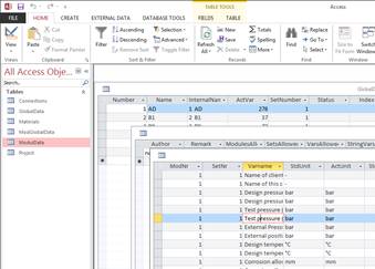
When you need these solutions in your present project you may easily import single modules or the whole file by merging it into the current project.
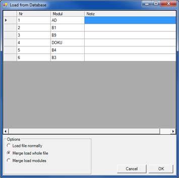
Mark the chapters with CTRL + pressed left mouse button.
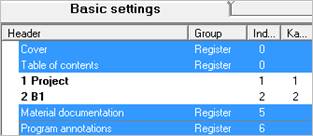
Cover
A cover is added to your documentation. You must specify the cover in the print menu under Print –
Table of Contents (TOC)
Selecting "Table of contents" creates a table of contents in the printout. It consists of the headlines of all the chapters to be printed, indicating the page numbers. Remarks from the notepad are used as prior headlines. The module name and description are quoted in brackets.
The Table of Contents contains also a legend, which shows how the different type of values are displayed. Input values, calculated values and estimated values are displayed differently for an easy identification.
Material documentation
If material data has been integrated from the database into a project, these data are documented in the annex. A separate documentation sheet is created for every material, different geometrical data, temperature or operating pressure.
Program annotations
A table of annotations is created on the last page of the document. It comprises all annotations and messages displayed by the program during the calculation.
Page number of 1st page
Set the number with which the numbering starts.
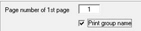
Print group name
The group name is printed before the chapter.
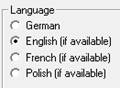
Select the printout language if the according masks are available or purchased.
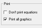
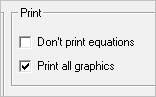
Equations from the input mask are printed by default. You may select not to print the equations.
Graphics from the input mask may be printed.
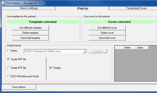
It is shown if a template and/or a cover is used for the next printout. They are saved with the ATL file.
Use different template / cover
Select a different template / cover for this printout.
Delete template / cover
Deletes the cover / template for this printout.
Show / edit template / cover
The cover / template used for this printout is displayed and can be edited and adjusted only for this printout. The changes are saved with the ATL file.
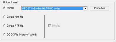
Printer
Set the local or network printer you want to use. All installed printers of your system are offered.
>> IMPORTANT: Do not use a PDF printer here!
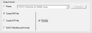
Create PDF file
If the box ‚Display‘ is ticked, the created PDF file is automatically opened with the installed PDF viewer.
Create RTF file (Word)
MS WORD is able to create an automatic table of contents in the RTF file you have printed. You may add additional text or graphics and then let Word refresh the automatic TOC.
Create DOCX file
Creates a native Microsoft Word file. DOCx was introduced in Word 2007 and is standard file extension if word nowadays.
See Insert place holders
Select File - Print and then the tab Template/Cover and Create custom template
or Options – Create template
The default template is opened with the editor (Template.tx).
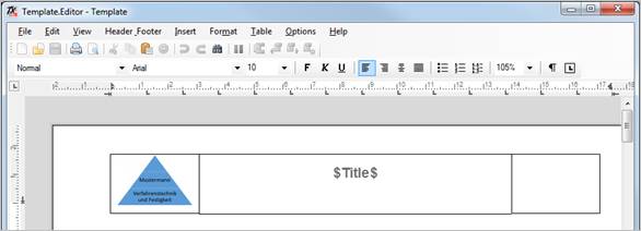
The templates are in .tx format and you can only edit them with the internal LV editor.
The default template is only a suggestion. You can easily change the logo and enter your company name in the header or footer. Adjust the appearance according to your requirements.
>> Everything you write into the body of the template will be overwritten when printing.
Note
The place holder $Title$ will be replaced by the actual file name of the ATL calculation file in the printout. If you delete this placeholder the name will not be printed in future printouts.
You may also load your own templates as RTF files in the editor and edit them.
The template can be adjusted to fit to your standard company paper with printed header and footer.
>> Adjust the height and size of header and footer to fit your paper size.
The following file types can be loaded into the LV editor and then saved in TX format for the LV program. This allows you to adjust the documentation to existing company templates.
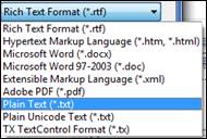
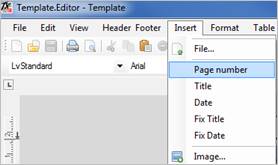
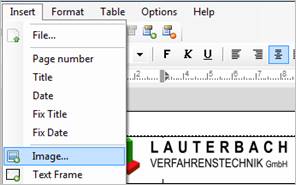
With the ‚Insert‘ command you can insert the following standard place holders into the template:
|
Page number |
|
|
Title |
Actual file name as title |
|
Date |
The current date is used for printing. |
|
Fix Title |
Fix title. Independent of the file name of the calculation file. |
|
Fix Date |
One time fixed date. |
Insert any placeholders
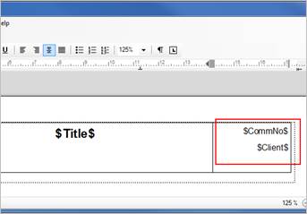
By using the format $placeholder$ you can enter any desired placeholder into your template or cover. You may then enter values for these placeholders in your printing form the values is printed instead of the placeholder.

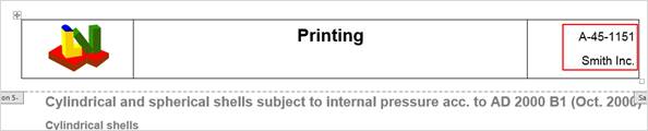
You can print the file name of the ATL file to the header or the footer. Place the cursor where you want to insert the file name.
Select in the editor
Insert – Title For the actual file name (especially after renaming and saving)
Insert – Fix Title For a one time title
You can print the current date or a one-time date. Place the cursor where you want to insert the date
Select in the editor
Insert – Date For the current date (will be updated for every printout)
Insert – Fix Date For a one-time date.
To insert your logo in the header or footer please select ‚Insert – Image‘
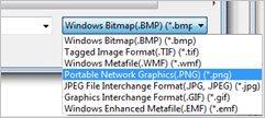
Select the image type of your logo (jpg, bmp, wmf, etc)
The printing template is saved with the ATL file. You can edit it individually for the next printout. For example you can add a commission number on every page which is only valid for this calculation.
Select the ‚Print to‘ tab
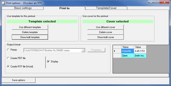
You may
1. Use the default template you have created
2. Use a different template for tis printout
3. Delete the template and print without a template
You can see at an instant if you have selected a template or not. With the button Show / edit template you can even see which template you will be using.
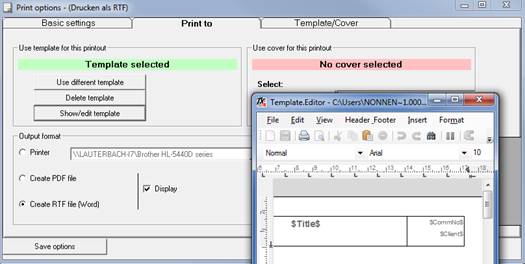
You can edit the template for this printout. The template is saved with the ATL file and is available the next time you open the ATL file.
Select the tab Template/Cover and Create own cover.
The default cover (Cover.tx) is opened in the LV editor.
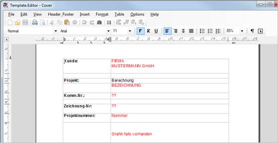
The cover is in .tx format and you can only edit them in the internal LV editor. The default cover is only a suggestion for further processing.
Editing the cover is similar to editing a document in MS Word. Despite when editing the template you can use the complete sheet. The cover is set in front of the documentation when selected.
You have the same features as when editing the template, including all place holders.
The cover is saved with the ATL calculation file. It can be edited individually.
Select the Print to tab.
You may
1. Use the default cover you have created
2. Use a different cover for this printout
3. Delete the cover and print without a cover
You can see at an instant if you have selected a cover or not. With the button Show / edit cover you can even see which cover you will be using
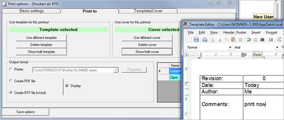
You can edit the cover for this printout. The cover is saved with the ATL file and is available the next time you open the ATL file.
'Feezing' means that you pay a fee for using software without the need to purchase it. the big advantage is the fact that you can mix 'Feezing' modules with purchased modules:
You buy the most frequently needed modules and use rarely needed modules by 'Feezing'. A fee is billed not for using the program but for performing certain program actions (starting, printing and saving).
There are two possibilities for billing via 'Feezing':
1.) With an existing Internet connection, the fees can be debited directly from the LV customer account by normal http-protocol. There is only a minimum of data exchange restricted to account information at the beginning and at the end of an LV session. There is no data transfer while calculating a project. Project data are not transferred via Internet. These data are safely located on yor computer.
2.) Without Internet connection (e.g. at the construction site or at work stations with a high security requirement) thefees can be debited from a smartcard. This smartcard (similar to a phone card or cash card) is connected to your PC by a smartcard reader. The card can be recharged by the customer itself or sent by mail by LV.
At first the program checks if a smart card is connected or not.
If no smartcard is available or you do not want to use it, the price list is loaded via internet.
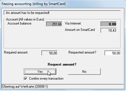
For the first action you are requested to transfer an amount from your LV account to your PC.
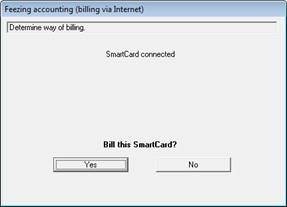
You generate a local sub-account. You can request any amount of money ranging from the necessary amount for calculation and the amount you have on your account.
The process which is being cashed up at the moment is printed in bold – in our example the module B1 (cylindrical and spherical shells under internal pressure) is to be executed.
Please note that every transaction is at least 1 EUR!
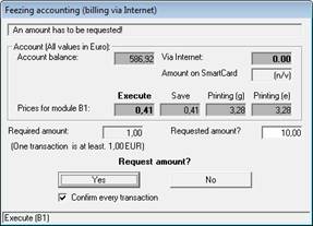
A customer account with LV is the basic requirement for "Feezing" !
Using the Feezing menu allows you to have a look at the price list and your balance and statement of your account. You can find it in 'FEEZING' menu of the input mask .
Price list and balance can be shown instantly. A statement requires an internet connection. The program lets you state the period of time for which you need the statement or offers to show you all transactions done after previous printing of a statement.
Once the balance has been loaded it can be shown instantly without connecting to the internet. Use the ‘refresh’ button, to request the balance via internet.
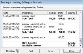
You see a warning on screen if there is only little money left on your account. It is necessary that you pay as much money into your account as you need for processing your calculations. If there is no money left on your account, you are not able to use the desired features of our programs! The amount of money you need can be paid in advance by a simple banking transaction or directly by VISA during our usual office times.
You don’t need an internet connection as long as if there is enough money on your local sub-account. Every transaction is made via your local sub-account.
By activating the check box ‘Confirm every transaction’ also the transactions via your local sub-account are confirmed – after deactivating the check box you only have to confirm the procedures requiring an internet connection. If there is not enough money on your local sub-account for performing your calculation, the amount of money on your local sub-account is automatically transferred to your personal account via the internet. Then you can transfer the amount of money you need to your local sub-account.
If you change the computer you are using our programs with, you must transfer the whole amount of money from your local sub-account to your personal account on our server.
After terminating the program package, the still existing amount of money on your local sub-account is also transferred to your personal account. This requires an internet connection. If you abort this transaction or don’t want to connect to the internet, the money will be transferred next time when you are loading the price list.
Please install the card reader drivers from the LV program CD:
[CD drive]:\Support\Smartcard\32bit\setup.exe
[CD drive]:\Support\Smartcard\32bit\setup.exe
All actions billed via smart card are stored. This protocol has got nothing to do with your accout balance. You can call up the protocol in the "Feezing" menu.
All actions are marked with the smartcard ID, name of the PC and name of the user of the smartcard.
The smartcard can be recharged via Internet. Select the "Load Smartcard" menu item in the "Feezing" menu.
As soon as you have stated the amount you want to transfer to your card, an Internet connection is established and the stated amount is transferred.
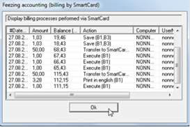
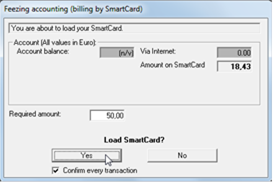
The transferred amount is protocolled in the account balance and in the smart card protocol with the according smartcard ID.
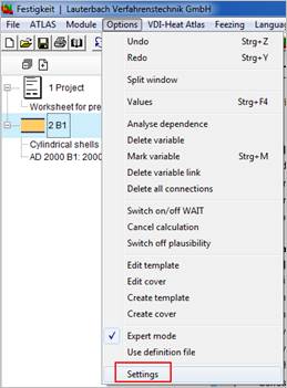
The appearance of the software can be adjusted with the settings dialogue.
· in the 'Options' menu click on 'Settings'
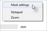
· right mouse click on an empty space of the input mask
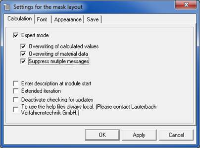
In expert mode you can use some additional features. These features require a certain familiarity with the LV Atlas program system.
An equation always consists of several given values and exactly one value to be calculated. The LV equation solver allows to calculate any desired variable of an equation. That is why it is possible to overwrite a calculated value and changing this value into a input value.
The equation is now over-determined. The program shows a list of former input values. Clear one of these values. The cleared value will now be calculated prospectively.
You can switch this option off to simplify the input in an LV module. When you are getting used to the operation of the LV software you should switch on this option. This option is a very good tool for the optimization of a technical part.
The material data, which is provided by the program’s database, can be overwritten with your own data. This can be advantageous if you have a material certificate with higher strength values than of the integrated standard. (see: Special case: Material data
By activating this option, all program messages are displayed in the InfoBrowser. You can find them in the 'messages' tab. Program messages are warnings, error messages, hints and annotations.
Wens starting a calculation module you are prompted to enter a name for this module.
Some values have to be determined by iteration. The program look for a solution within determined borders. E.g. the inside diameter of a tube lies always within zero and the outside diameter. it doesn’t make sense to look for a solution outside these borders.
To find out that for example the inside diameter could be slightly larger than the outside diameter under the given conditions, it can sometimes be helpful to look for solutions beyond these borders. in this case the input value can be corrected and the solution is valid again.
if this option is switched on, the program marks all values, which are beyond the borders of their validity after the calculation.
This option is not saved and is switched off by default.
The prigram checks if there is a new version available. You can switch off this check here.
Some values are displayed but cannot be changed.
The fileds of these variables are locked. that means you can see the value but you do not have access.
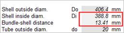
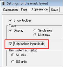
Locked fields can be activated by unticking the according Box.
Strength calculation modules receive data from the material data base to determine the material properties according the regulation.
It is sufficient to enter the material name. The program determines the characteristics dependent on operating temperature, or e.g. wall thickness. By deafult the fields of the determined material characteristics are locked.
If you need to enter deviant characteristics (e.g. for safety reasons or special materials), You have to change the values entered by the program.
This is only possible in 'Expert mode'. The box 'Overwriting of material data' must be ticked.
Material characteristics which have been changed by the user, are displayed and printed in red.
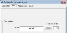
Here you can select the font of the input mask freely.
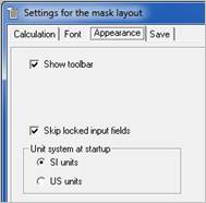
You can switch on or off the toolbar. You can skip locked inout fields and you can change the dlobal unit system.
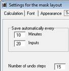
You can specify when the program should save your data. Enter the time or the number of inputs after which the program saves automatically.
The number of undo steps can be entered freely.
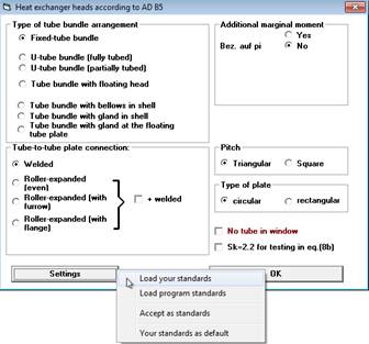
In some modules you need to specify the type at the module start. You can save frequently nedded types as your standard and load them at program start by 'Settings'.
If you have selected 'Your standards as default' the selection form will start with your settings the next time you start the module.
Advantage:
Frequently used types can be selected quickly.
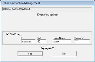
Most company networks are connected to the internet by their own server (gateway). On this server there might be running a proxy server program and a firewall.
You need to set up a proxy server in the Windows control panel under internet options / connections. Ask your administrator.
A firewall may be set up to ignore requests from the Lauterbach Verfahrenstechnik GmbH program to get information from the internet.
In this case the program shows a fprm where you can enter your proxy settings.Please ask your system administrator for your Proxy Settings.
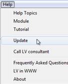
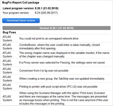
You can find program changes and bugfixes of the last 90 days at:
'Help' / 'Update'
You can update your software within a service contract simply via the internet.
The following information is displayed: No update necessary: Cancel
or
an update is available
The version number is displayed. New program features and bug fixes can be found on our web site.
The Next button starts the update procedure.
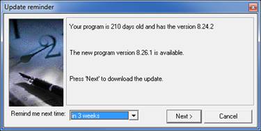
Your internet browser is started, and an Internet connection to our update server is established.
If the connection is established successfully an Internet site wit hthe change log and bug fixes is shown and if you have a valid service maintenance contract a Link to the Download of the latest version is displayed as well.

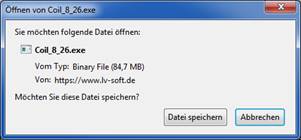
Save the file on your computer.
Install the update by running the downloaded file (administration rights arerequired).
Please close the LV program before installing the update!
The software is unlocked by a license file (.lic) you have received by email. See: Activation of the software license (*.LIC file
Select 'Call LV consultant' from the 'Help' menu. Please make sure you can establish an internet connection.
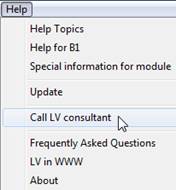
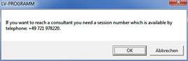
Confirm with OK.
Call LV and let your consultant know your ID and your password
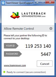
Our hotline is essential in our customer service. Our engineers who have developed the LV programs and who work with this software every day are your contact persons.
Scope of service
1. For our customers a free of charge hotline for questions concerning operation of the program is provided for 30 days from date of purchase.
2. After that time we offer support at a very competitive price, covering technical as well as specific questions.
3. Within a concluded service contract, usual user requests are included.
You can reach the LV team Monday to Friday from 09.00 am to 4.00 p.m. by phone.
|
Phone: |
+ 49 - 721 - 97 82 20 |
|
Fax: |
+ 49 - 721 - 78 21 06 |
|
Email: |
info@LV-soft.de |
|
http://www.LV-soft.com |