Variable list
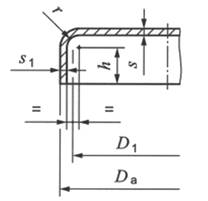
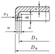
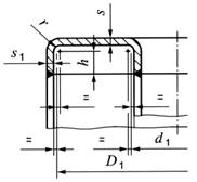
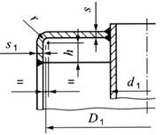
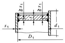
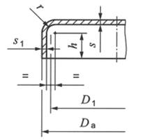
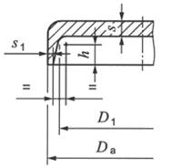
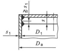
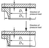
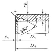
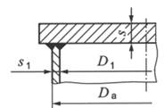
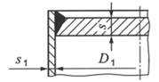
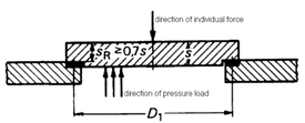
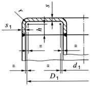
Table 1 – Design factors of flat ends without additional boundary moment
|
Type |
Conditions |
Design |
||||||||||||||
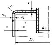
a) flanged flat end
|
1. Knuckle radius:
2. Cylindrical part: h ≥ 3,5s (Please note conditions from section 6.1.1!) |
0,30 |
||||||||||||||
|
b) forged or pressed flat end
|
1. Knuckle radius However at least 8 mm. 2. Cylindrical part h ≥ s |
0,35 |
||||||||||||||
|
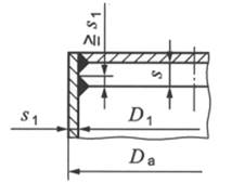
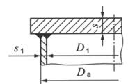
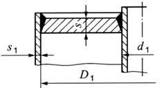
c) flat plate welded into the shell from both sides
|
Plate thickness |
|
||||||||||||||
|
s ≤ 3 s1 |
0,35 |
|||||||||||||||
|
s > 3 s1 |
0,40 |
|||||||||||||||
|
d) bolted flat plate with full face gasket
|
D1 ≥ Di |
0,35 |
||||||||||||||
|
e) flat plate with stress-relieve groove 1)
s1= Final wall thickness of cylindrical part of the end connected to the shell. |
1. Residual wall thickness in the groove:
not less than 5 mm and with Da > 1,2 D1 sR ≤ 0,77 s1 2. Groove radius: r ≥ 0,2 s, however not less than 5 mm and 3. Only killed steels may be utilized. When plate material is employed over an area of at least 3 s1 in the weld zone there must be no evidence of material discontinuities in the plate 2). 4. For special loads e.g. creep structure strength, this type is inappropriate without extra proof. |
0,40 |
||||||||||||||
|
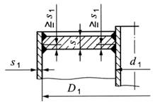
f) flat plate welded onto the shell from both sides
|
Plate thickness: |
|
||||||||||||||
|
s ≤ 3 s1 |
0,40 |
|||||||||||||||
|
s > 3 s1 |
0,45 |
|||||||||||||||
|
Only killed steels may be utilized. When plate material is employed over an area of at least 3 s1 in the weld zone there must be no evidence of material discontinuities in the plate 2). |
|
|||||||||||||||
|
g) simply supported flat plate
|
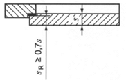
Residual wall thickness at the gasket circle or at the grooves sR ≥ 0,7 s |
0,40 |
||||||||||||||
|
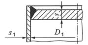
h) flat plate welded into the shell from one side only
|
Plate thickness: |
|
||||||||||||||
|
s ≤ 3 s1 |
0,45 |
|||||||||||||||
|
s > 3 s1 |
0,50 |
|||||||||||||||
|
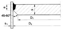
i) partially-welded flat plate
|
Plate thickness: |
|
||||||||||||||
|
s ≤ 3 s1 |
0,45 |
|||||||||||||||
|
s > 3 s1 Conditions for a: a ≥ 0,5 s and a ≥ 1,4 s1 Df /D1 ≥ 0,7 |
0,50 |
|||||||||||||||
|
k) flat plate attached from the external side
|
1. Residual plate thickness at gasket
circle: 2. Soft gasket |
1,25 |
||||||||||||||
|
l) flat plate attached from the internal side
|
Residual wall thickness at gasket circle: sR ≥ 0,7 s |
0,45 |
||||||||||||||
|
1) Stress-relieve grooves with different cross section may be more effective in reducing stresses and are acceptable if appropriate evidence is produced. 2) As rule this is the case when the inspections are carried out as specified in EN 10160 quality class 3. This can be stipulated at the time when the order is placed. |
||||||||||||||||
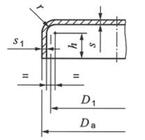
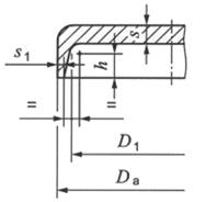

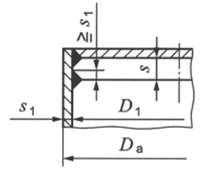
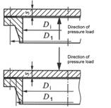
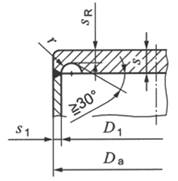

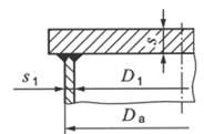
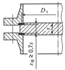
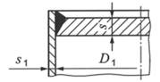
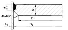
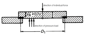
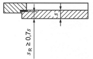
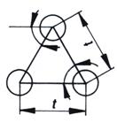
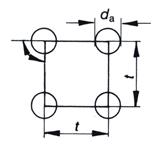
Table 1 – Design factors of flat ends without additional boundary moment
|
Type |
Conditions |
Design |
||||||||||||||
a) flanged flat end
|
1. Knuckle radius:
2. Cylindrical part: h ≥ 3,5s (Please note conditions from section 6.1.1!) |
0,30 |
||||||||||||||
|
b) forged or pressed flat end
|
1. Knuckle radius However at least 8 mm. 2. Cylindrical part h ≥ s |
0,35 |
||||||||||||||
|
c) flat plate welded into the shell from both sides
|
Plate thickness |
|
||||||||||||||
|
s ≤ 3 s1 |
0,35 |
|||||||||||||||
|
s > 3 s1 |
0,40 |
|||||||||||||||
|
d) bolted flat plate with full face gasket
|
D1 ≥ Di |
0,35 |
||||||||||||||
|
e) flat plate with stress-relieve groove 1)
s1= Final wall thickness of cylindrical part of the end connected to the shell. |
1. Residual wall thickness in the groove:
not less than 5 mm and with Da > 1,2 D1 sR ≤ 0,77 s1 2. Groove radius: r ≥ 0,2 s, however not less than 5 mm and 3. Only killed steels may be utilized. When plate material is employed over an area of at least 3 s1 in the weld zone there must be no evidence of material discontinuities in the plate 2). 4. For special loads e.g. creep structure strength, this type is inappropriate without extra proof. |
0,40 |
||||||||||||||
|
f) flat plate welded onto the shell from both sides
|
Plate thickness: |
|
||||||||||||||
|
s ≤ 3 s1 |
0,40 |
|||||||||||||||
|
s > 3 s1 |
0,45 |
|||||||||||||||
|
Only killed steels may be utilized. When plate material is employed over an area of at least 3 s1 in the weld zone there must be no evidence of material discontinuities in the plate 2). |
|
|||||||||||||||
|
g) simply supported flat plate
|
Residual wall thickness at the gasket circle or at the grooves sR ≥ 0,7 s |
0,40 |
||||||||||||||
|
h) flat plate welded into the shell from one side only
|
Plate thickness: |
|
||||||||||||||
|
s ≤ 3 s1 |
0,45 |
|||||||||||||||
|
s > 3 s1 |
0,50 |
|||||||||||||||
|
i) partially-welded flat plate
|
Plate thickness: |
|
||||||||||||||
|
s ≤ 3 s1 |
0,45 |
|||||||||||||||
|
s > 3 s1 Conditions for a: a ≥ 0,5 s and a ≥ 1,4 s1 Df /D1 ≥ 0,7 |
0,50 |
|||||||||||||||
|
k) flat plate attached from the external side
|
1. Residual plate thickness at gasket
circle: 2. Soft gasket |
1,25 |
||||||||||||||
|
l) flat plate attached from the internal side
|
Residual wall thickness at gasket circle: sR ≥ 0,7 s |
0,45 |
||||||||||||||
|
1) Stress-relieve grooves with different cross section may be more effective in reducing stresses and are acceptable if appropriate evidence is produced. 2) As rule this is the case when the inspections are carried out as specified in EN 10160 quality class 3. This can be stipulated at the time when the order is placed. |
||||||||||||||||
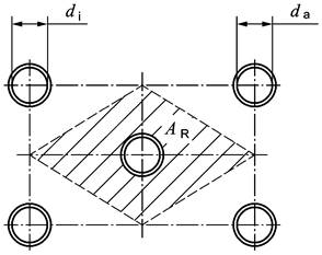
Loaded Area AR
Table 2 – Design factors of circular flat ends and plates with a central stay bolt or tube
|
Type |
Conditions |
Design |
||||||||||||||
Flanged flat end a) with inward flange
or b) with protruding stay
|
1. Knuckle radius:
2. Cylindrical part: h ≥ 3,5s (Please note conditions from section 6.5.1!)
|
0,25 |
||||||||||||||
|
c) flat plate welded into the shell from both sides with protruding stay
|
Plate thickness |
|
||||||||||||||
|
s ≤ 3 s1 |
0,30 |
|||||||||||||||
|
s > 3 s1 |
0,35 |
|||||||||||||||
|
d) flat plate welded into the shell from one side with protruding stay
|
Plate thickness |
|
||||||||||||||
|
s ≤ 3 s1 |
0,40 |
|||||||||||||||
|
s > 3 s1 |
0,45 |
|||||||||||||||
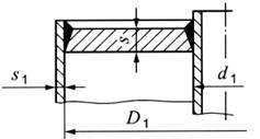
Annex 1 Table 1 – Determination of l
|
Type of tubing |
Sketch |
|
A)
Fully-tubed tubesheet |
_ _ _ Fixation ____ Circle with the diameter 2 ·l1 + da |
|
B)
Circular segment
|
_ _ _ Fixation ____ Centre of outer tubes |
|
Type of tubing |
Sketch |
|
C)
Rectangle/Arc
|
_ _ _ Fixation ____ Centre of outer tubes |
|
D) Circular
sector
|
_ _ _ Fixation ____ Centre of outer tubes |
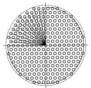
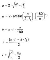
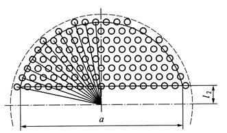
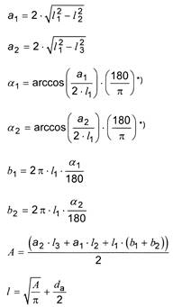
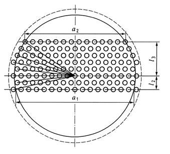

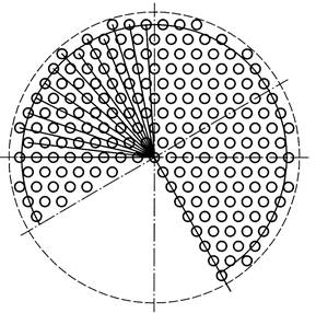
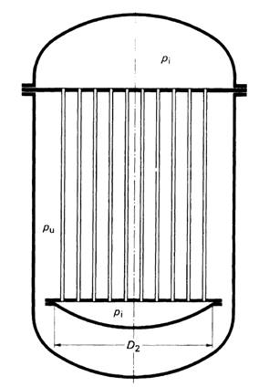
Fig 15. Circular, flat plates of floating head heat exchangers
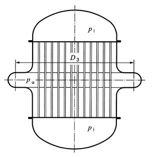
Figure 17 – Circular, flat plates on heat exchangers with an expansion joint in the shell
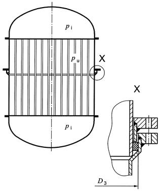
Figure 18 – Circular, flat plates on heat exchangers with a gland in the shell
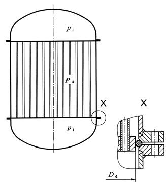
Figure 19 – Circular, flat plates on heat exchangers with a gland at the floating tubesheet
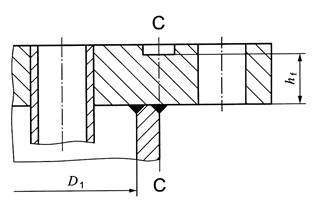
Figure 20 – Circular, flat plates with protruding flange edge
Table 1 – Design factors of flat ends without additional boundary moment
|
Type |
Conditions |
Design |
||||||||||||||
a) flanged flat end
|
1. Knuckle radius:
2. Cylindrical part: h ≥ 3,5s (Please note conditions from section 6.1.1!) |
0,30 |
||||||||||||||
|
b) forged or pressed flat end
|
1. Knuckle radius However at least 8 mm. 2. Cylindrical part h ≥ s |
0,35 |
||||||||||||||
|
c) flat plate welded into the shell from both sides
|
Plate thickness |
|
||||||||||||||
|
s ≤ 3 s1 |
0,35 |
|||||||||||||||
|
s > 3 s1 |
0,40 |
|||||||||||||||
|
d) bolted flat plate with full face gasket
|
D1 ≥ Di |
0,35 |
||||||||||||||
|
e) flat plate with stress-relieve groove 1)
s1= Final wall thickness of cylindrical part of the end connected to the shell. |
1. Residual wall thickness in the groove:
not less than 5 mm and with Da > 1,2 D1 sR ≤ 0,77 s1 2. Groove radius: r ≥ 0,2 s, however not less than 5 mm and 3. Only killed steels may be utilized. When plate material is employed over an area of at least 3 s1 in the weld zone there must be no evidence of material discontinuities in the plate 2). 4. For special loads e.g. creep structure strength, this type is inappropriate without extra proof. |
0,40 |
||||||||||||||
|
f) flat plate welded onto the shell from both sides
|
Plate thickness: |
|
||||||||||||||
|
s ≤ 3 s1 |
0,40 |
|||||||||||||||
|
s > 3 s1 |
0,45 |
|||||||||||||||
|
Only killed steels may be utilized. When plate material is employed over an area of at least 3 s1 in the weld zone there must be no evidence of material discontinuities in the plate 2). |
|
|||||||||||||||
|
g) simply supported flat plate
|
Residual wall thickness at the gasket circle or at the grooves sR ≥ 0,7 s |
0,40 |
||||||||||||||
|
h) flat plate welded into the shell from one side only
|
Plate thickness: |
|
||||||||||||||
|
s ≤ 3 s1 |
0,45 |
|||||||||||||||
|
s > 3 s1 |
0,50 |
|||||||||||||||
|
i) partially-welded flat plate
|
Plate thickness: |
|
||||||||||||||
|
s ≤ 3 s1 |
0,45 |
|||||||||||||||
|
s > 3 s1 Conditions for a: a ≥ 0,5 s and a ≥ 1,4 s1 Df /D1 ≥ 0,7 |
0,50 |
|||||||||||||||
|
k) flat plate attached from the external side
|
1. Residual plate thickness at gasket
circle: 2. Soft gasket |
1,25 |
||||||||||||||
|
l) flat plate attached from the internal side
|
Residual wall thickness at gasket circle: sR ≥ 0,7 s |
0,45 |
||||||||||||||
|
1) Stress-relieve grooves with different cross section may be more effective in reducing stresses and are acceptable if appropriate evidence is produced. 2) As rule this is the case when the inspections are carried out as specified in EN 10160 quality class 3. This can be stipulated at the time when the order is placed. |
||||||||||||||||
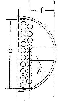
No-tubes-in-window tube sheets with tubes acting as mutual anchorage
It is assumed that the forces due to pressure are transferred equally to
· the shell and
· two tube rows
i.e. at the widest location there is a loaded area for one tube of:
ARohr = AF / 4 = t * f/2 = 0.5 * t * f
t = pitch (see AD 2000-Merkblatt B 5)
If there is a groove, you have to add the depth of the groove to the calculated thickness.
Annex 1 Table 1 – Determination of l
|
Type of tubing |
Sketch |
|
A)
Fully-tubed tubesheet |
_ _ _ Fixation ____ Circle with the diameter 2 ·l1 + da |
|
B)
Circular segment
|
_ _ _ Fixation ____ Centre of outer tubes |
|
Type of tubing |
Sketch |
|
C)
Rectangle/Arc
|
_ _ _ Fixation ____ Centre of outer tubes |
|
D) Circular
sector
|
_ _ _ Fixation ____ Centre of outer tubes |
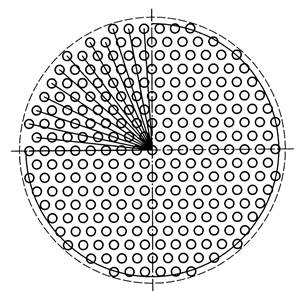
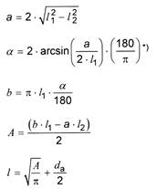
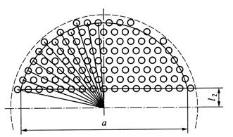
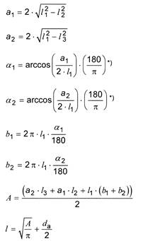
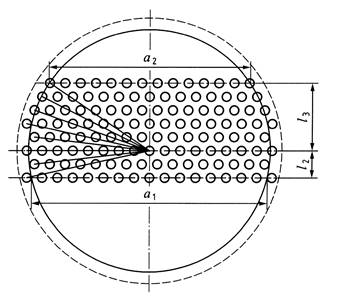

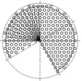
Table 1 – Design factors of flat ends without additional boundary moment
|
Type |
Conditions |
Design |
||||||||||||||
a) flanged flat end
|
1. Knuckle radius:
2. Cylindrical part: h ≥ 3,5s (Please note conditions from section 6.1.1!) |
0,30 |
||||||||||||||
|
b) forged or pressed flat end
|
1. Knuckle radius However at least 8 mm. 2. Cylindrical part h ≥ s |
0,35 |
||||||||||||||
|
c) flat plate welded into the shell from both sides
|
Plate thickness |
|
||||||||||||||
|
s ≤ 3 s1 |
0,35 |
|||||||||||||||
|
s > 3 s1 |
0,40 |
|||||||||||||||
|
d) bolted flat plate with full face gasket
|
D1 ≥ Di |
0,35 |
||||||||||||||
|
e) flat plate with stress-relieve groove 1)
s1= Final wall thickness of cylindrical part of the end connected to the shell. |
1. Residual wall thickness in the groove:
not less than 5 mm and with Da > 1,2 D1 sR ≤ 0,77 s1 2. Groove radius: r ≥ 0,2 s, however not less than 5 mm and 3. Only killed steels may be utilized. When plate material is employed over an area of at least 3 s1 in the weld zone there must be no evidence of material discontinuities in the plate 2). 4. For special loads e.g. creep structure strength, this type is inappropriate without extra proof. |
0,40 |
||||||||||||||
|
f) flat plate welded onto the shell from both sides
|
Plate thickness: |
|
||||||||||||||
|
s ≤ 3 s1 |
0,40 |
|||||||||||||||
|
s > 3 s1 |
0,45 |
|||||||||||||||
|
Only killed steels may be utilized. When plate material is employed over an area of at least 3 s1 in the weld zone there must be no evidence of material discontinuities in the plate 2). |
|
|||||||||||||||
|
g) simply supported flat plate
|
Residual wall thickness at the gasket circle or at the grooves sR ≥ 0,7 s |
0,40 |
||||||||||||||
|
h) flat plate welded into the shell from one side only
|
Plate thickness: |
|
||||||||||||||
|
s ≤ 3 s1 |
0,45 |
|||||||||||||||
|
s > 3 s1 |
0,50 |
|||||||||||||||
|
i) partially-welded flat plate
|
Plate thickness: |
|
||||||||||||||
|
s ≤ 3 s1 |
0,45 |
|||||||||||||||
|
s > 3 s1 Conditions for a: a ≥ 0,5 s and a ≥ 1,4 s1 Df /D1 ≥ 0,7 |
0,50 |
|||||||||||||||
|
k) flat plate attached from the external side
|
1. Residual plate thickness at gasket
circle: 2. Soft gasket |
1,25 |
||||||||||||||
|
l) flat plate attached from the internal side
|
Residual wall thickness at gasket circle: sR ≥ 0,7 s |
0,45 |
||||||||||||||
|
1) Stress-relieve grooves with different cross section may be more effective in reducing stresses and are acceptable if appropriate evidence is produced. 2) As rule this is the case when the inspections are carried out as specified in EN 10160 quality class 3. This can be stipulated at the time when the order is placed. |
||||||||||||||||
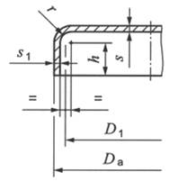
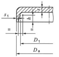
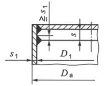
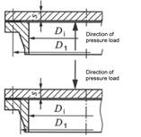
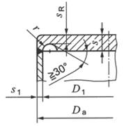
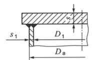
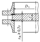
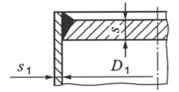
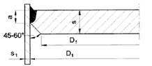
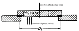

Table 2 – Design factors of circular flat ends and plates with a central stay bolt or tube
|
Type |
Conditions |
Design |
||||||||||||||
Flanged flat end a) with inward flange
or b) with protruding stay
|
1. Knuckle radius:
2. Cylindrical part: h ≥ 3,5s (Please note conditions from section 6.5.1!)
|
0,25 |
||||||||||||||
|
c) flat plate welded into the shell from both sides with protruding stay
|
Plate thickness |
|
||||||||||||||
|
s ≤ 3 s1 |
0,30 |
|||||||||||||||
|
s > 3 s1 |
0,35 |
|||||||||||||||
|
d) flat plate welded into the shell from one side with protruding stay
|
Plate thickness |
|
||||||||||||||
|
s ≤ 3 s1 |
0,40 |
|||||||||||||||
|
s > 3 s1 |
0,45 |
|||||||||||||||
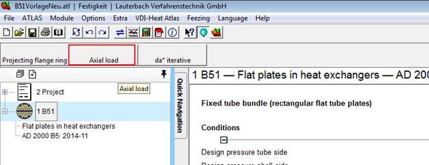
To determine this value, press the ‚Axial load‘ switch.