BEIN
|
Fig.1 Container on supports |
|
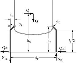
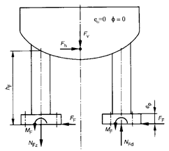 Fig. 2:
Special case
Fig. 2:
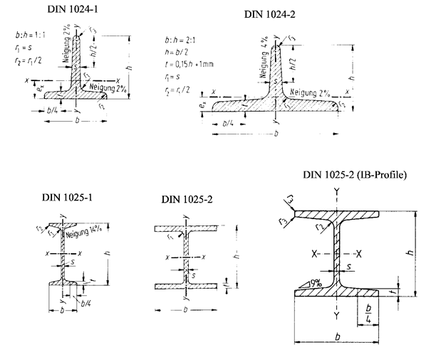
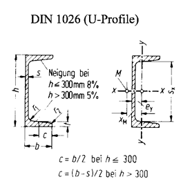
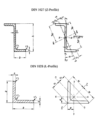
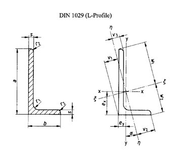
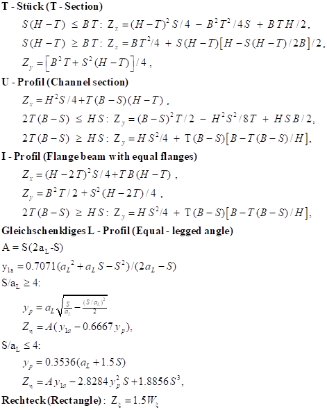
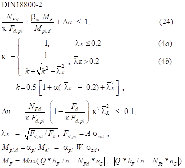
Special caseThe load on the supports of a container is calculated according to AD-S3/0 and evaluated for standard profiles according to DIN 1024 ... 1029 are evaluated. Weight forces G and shear forces Q can be specified. If the maximum normal force according to AD-S3/3 is exceeded, a stability verification according to DIN 18800 part 2 is performed.
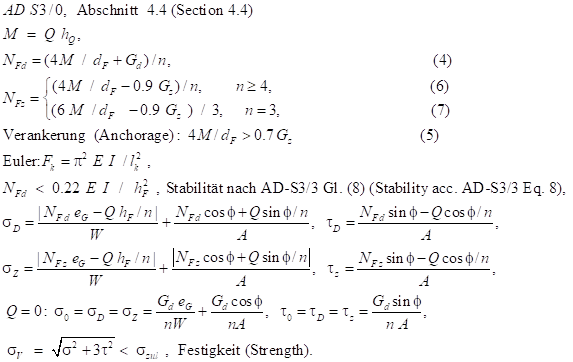
· With uniform support on n feet or claws, the maximum compressive force NFd on a single element can be calculated according to AD-S30 Section 4.4.
· Anchoring is necessary if 4M/dF > 0.7 Gz Eq. (5)
· The maximum tractive force is NFz
· If no uniform load distribution can be ensured by the support, n=3 at the most must be calculated!
· The Euler buckling force Fk is calculated according to Dubbel paperback Maschinenbau, Springer 1997, Chapter C Strength of Materials, p.42.
· The equations for the profile stresses s D, tD compressive and s Z, tZ tensile result from the static equilibrium conditions.
· For the case j=0 and eG=0, the bending stress corresponds to Code of Practice AD S3/3, equation (7a).
· According to AD-S3/3, the stability verification according to DIN 18800/2 can be omitted for NFd<0.22*EF*IF/hF^2
· The load on the base plate can be calculated according to AD-S3/3 with module S33.
|
Kink line |
a |
b |
c |
d |
|
a |
0.21 |
0.34 |
0.49 |
0.76 |
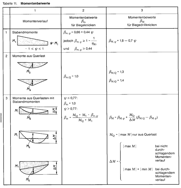
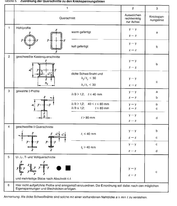
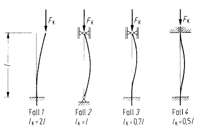
Fig.: Eulerian load cases
|
4.2 Load case |
BF1 |
BF2 |
PF1 |
PF2 |
MF1 |
MF2 |
SF1 |
SF2 |
... |
Sect. |
|
Dead load |
x |
x |
x |
x |
x |
x |
x |
x |
4.1.4.1 |
|
|
Internal pressure |
x |
x |
x |
4.1.4.2 |
||||||
|
Negative pressure |
x |
x |
x |
x |
||||||
|
Local pressure |
x |
|||||||||
|
Temperature |
x |
x |
4.1.4.3 |
|||||||
|
External load |
x |
x |
x |
x |
x |
x |
4.1.4.4 |
|||
|
Live load |
x |
x |
4.1.4.5 |
|||||||
|
Wind load |
x |
x |
x |
x |
x |
x |
4.1.4.6 |
|||
|
Snow load |
x |
x |
4.1.4.8 |
|||||||
|
Earthquake |
x |
x |
4.1.4.9 |
|||||||
|
Perm. voltage pressure vessel |
f |
fP |
fM |
fS |
4.3 |
|||||
|
Permissible voltage Support elements |
f |
1.1 f |
1.1 f |
1.5 f |
||||||
AD-S3/0 section 4.3.4, allowable calculation stress for pressure vessels; load case:
1. Operation: Permissible calculation voltage szul = f = K/S, K = characteristic value, S = safety factor according to AD-B0 during operation
2. Test case fP = K/S', S' = Safety factor Test case according to AD-B0
3. Assembly fM = K/SM, SM = S -a (S- S'); a = 1 for short-term load; a = 0.5 for longer load
4. Special case fS = K/SS, SS as for assembly with a = 1.25, but SS > 1.