Variable list
Empirical factor f1 in calculation of heat transfer coefficient a
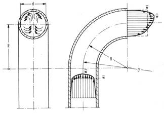
The factor f1 considers the influence of the tube curvature and the direction of the heat flux. The heat transfer coefficient in the coils is calculated with the mean velocity of the oil. s due to the curvature the velocity at the inner curvature side is smaller than the mean velocity, the heat transfer coefficient at the inner side of the curvature is also smaller than the mean heat transfer coefficient. This is considered by the factor f1. The f1 factor does only influence the calculation of the mean wall temperature of the inner coil and the increase of the temperature in the thermal boundary layer of the inner coil and te calculation of the maximum film temperature.
Therefore it is a mere safety factor. The f1 factor is calculated by default, but may also be entered by the user. f1 depends i.a. on the ratio di / Dw (tube inside diameter / coil diameter).
The decrease factor fA specifies the ratio of actual flame temperature and theoretical flame temperature

This factor is 0.8
fA = 0.77 for heating oils
fA = 0.80 for natural gas and liquid gas
Bending diameter in oil side pressure drop
The bending diameter is required for the calculation of the heat transfer coefficient of the coil.
The bending diameter (or the average diameter of curvature of the coil) is calculated as follows:
|
|
D |
bending diameter |
|
DW |
coil diameter |
|
|
h |
coil pitch (coil slope) |
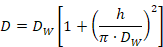
There is no significant difference between D and DW unless the tube is considerably bent and the pitch h is large.
We assume that heat in the furnace chamber is primarily transferred by radiation. Due to the curved surface of the tubes, the heat flux above the circumference of the tubes is not constant. As a result there is a tangential heat loss above the circumference of the tubes and a decrease in heat flux on the tube apex. This decrease is determined by the factor f0.
This temperature is used to determine the physical properties of the oil in the inner coil.
This temperature is used to determine the physical properties of the oil in the outer coil.
This factor enables the user to increase or decrease the calculated pressure drop. This feature is useful if you have comparative values for the pressure drop in existing exchangers.
At the beginning of the calculation the outlet temperature of the flue gas is set automatically by the program according to the flow pattern. (At counter-current flow 30 °C greater than the outlet temperature of the thermal oil and at co-current flow 30 °C greater than the inlet temperature of the thermal oil). The value can be overwritten by the user at any time.
With the option Iteration of flue gas outlet temperature' the actual outlet temperature is calculated to achieve an oversize of lesser than +/- 0.5 %.
The oversize is the ratio of total thermal performance / nominal thermal performance
This factor can be used to adjust the flame diameter to the actual flame diameter of the used burner.
This factor can be used to adjust the flame diameter to the actual flame length of the used burner.
The standard density ρN of natural gas depends on its composition. The standard density of pure methane is 0.72 kg/m³. By additional hydrocarbons (ethane: ρN = 1.36 kg/m³, propane: ρN = 2.01 kg/m³, n-butane: ρN = 2.71 kg/m³) and inert gases (nitrogen: ρN = 1.25 kg/m³, carbon dioxide: ρN = 1.98 kg/m³) the standard density increases. In the BREN module the standard density is set to 0.80 kg/m³. (Standard condition: 0 °C and 1.01325 bar)
The emissivity is set to 0.8 by default.