DECK module
Table 4 — Gasket material and contact widths: Gasket factors (m) for operating conditions and minimum design seating stress (y)
|
No. |
Gasket Material |
Gasket Factor |
Minimum design seating stress y |
|
|
1 |
Rubber with cotton fabric insertion |
1,25 |
2,8 |
|
|
2 |
Vegetable fibre |
1,75 |
7,6 |
|
|
3 |
Corrugated metal |
Soft aluminium |
2,75 |
25,5 |
|
4 |
Soft copper or brass |
3,00 |
31,0 |
|
|
5 |
Iron or soft steel |
3,25 |
37,9 |
|
|
6 |
Monel or 4 % to 6 % chrome |
3,50 |
44,8 |
|
|
7 |
Stainless steels |
3,75 |
52,4 |
|
|
8 |
Grooved metal profile |
Soft aluminium |
3,25 |
37,9 |
|
9 |
Soft copper or brass |
3,50 |
44,8 |
|
|
10 |
Iron or soft steel |
3,75 |
52,4 |
|
|
11 |
Monel or 4 % to 6 % chrome |
3,75 |
62,0 |
|
|
12 |
Stainless steels |
4,25 |
69,5 |
|
|
13 |
Flat metal profile |
Soft aluminium |
4,00 |
60,6 |
|
14 |
Soft copper or brass |
4,75 |
89,5 |
|
|
15 |
Iron or soft steel |
5,50 |
124 |
|
|
16 |
Monel or 4 % to 6 % chrome |
6,00 |
150 |
|
|
17 |
Stainless steels |
6,50 |
179 |
|
|
18 |
Ring joint |
Iron or soft steel |
5,50 |
124 |
|
19 |
Monel or 4 % to 6 % chrome |
6,00 |
150 |
|
|
20 |
Stainless steels |
6,50 |
179 |
|
|
21 |
Elastomer |
Natural rubber |
0,5 |
0 |
|
22 |
SWR |
0,5 |
0 |
|
|
23 |
Viton |
0,5 |
0 |
|
|
24 |
EPDM |
0,5 |
0 |
|
|
25 |
Silicon |
0,5 |
0 |
|
|
26 |
Neoprene |
1,0 |
1,38 |
|
|
27 |
Nitrile |
1,0 |
1,38 |
|
|
28 |
Butyl |
1,0 |
1,38 |
|
|
29 |
CNAF |
1,0 |
1,38 |
|
|
30 |
PTFE |
PTFE sheathing |
2,0 |
13,8 |
|
31 |
PTFE massive 1,5 mm |
2,75 |
25,4 |
|
|
32 |
PTFE massive 3 mm |
2,0 |
11,0 |
|
|
33 |
PTFE braided |
2,0 |
11,0 |
|
|
34 |
User-defined gasket specifications |
|||
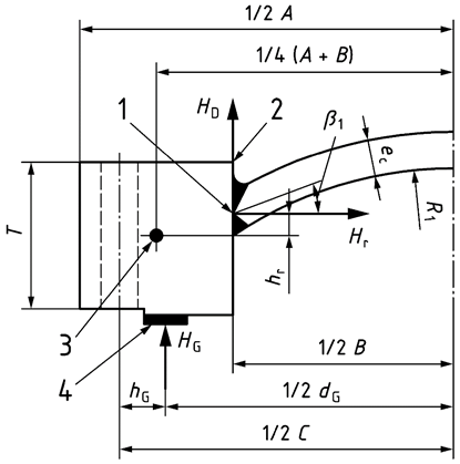
Key
1 Full penetration joint
2 Pivot of HD
3 Center
4 Appropriate gasket
Fig. 12 — Spherically dished bolted covers with a narrow-face gasket