EN 10 module
|
|
|
|
a) Uniform thickness shell |
b) Tapered shell |
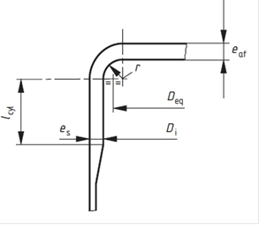
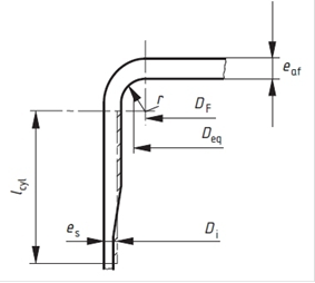
Fig. 10.4-1 – Circular flat ends with a hub
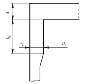
Fig. 10.4-2 – Circular flat ends welded
directly to the shell
(refer to Annex A for acceptable weld details)
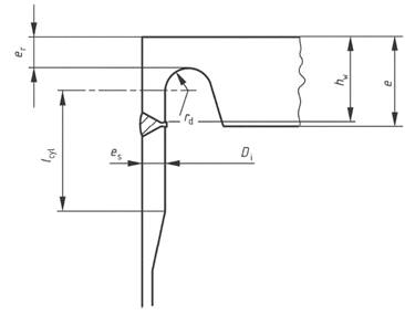
Fig. 10.4-3 – Circular flat ends with a relief groove
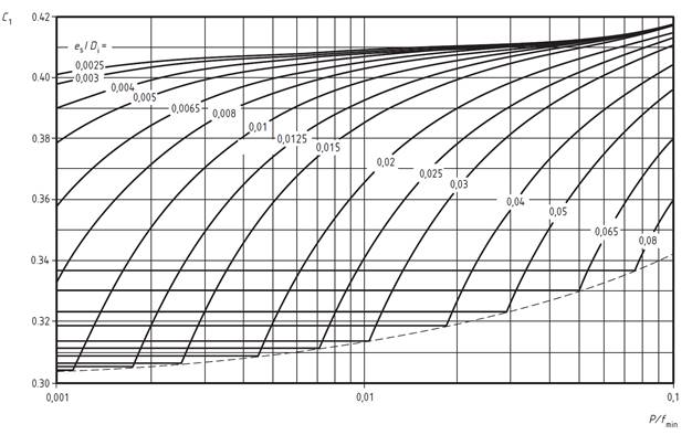
NOTE 1 Where P/fmin is lower than the value corresponding to the point of intersection between the es/Di curve and the bottom curve (dotted line), C1 is the value defined by the horizontal line passing through this point.
NOTE 2 There are cases where P/f shall be used instead of P/fmin
|
1 Plane face |
|
|
2) Raised face |
|
|
3) Tongued joint |
|
|
4) Grooved joint |
|
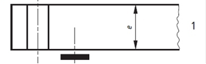
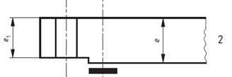
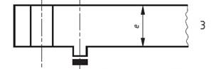
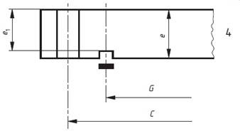
Fig. 10.5-1 – Bolted circular flat ends with a narrow-face gasket
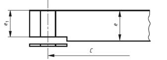
Fig. 10.5-2 – Bolted circular flat end with a full-face gasket
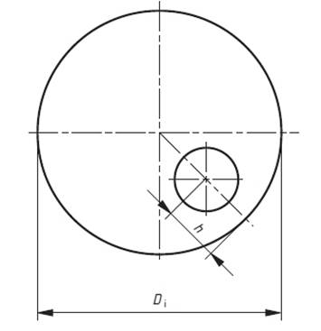
Fig. 10.6-1 – Single opening in a flat end
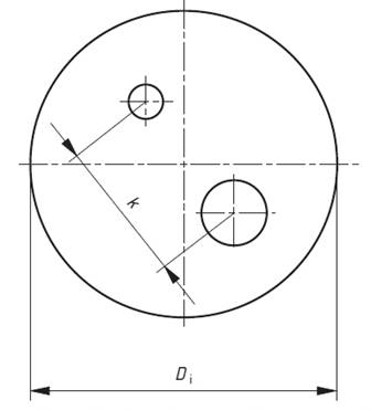
Fig. 10.6-2 – Pair of openings in a flat end
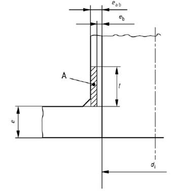
Fig. 10.6-3 – Set-on nozzle in a flat end
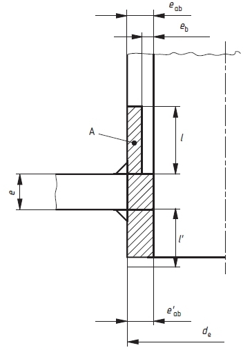
Fig. 10.6-4 – Set-in nozzle in a flat end
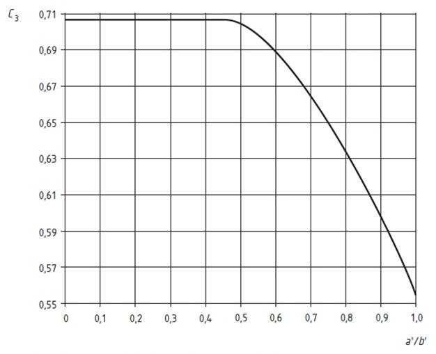
Fig. 10.7-1 – Shape factor C3 for welded non-circular flat ends
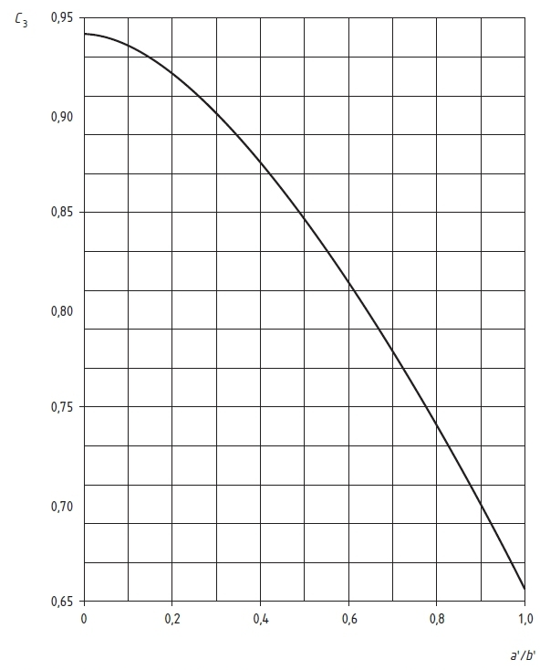
Fig. 10.7-2 – Shape factor C3 for bolted rectangular flat end with full-face gasket
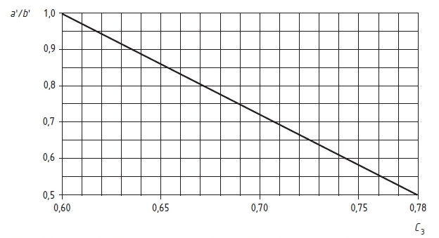
Fig. 10.7-3 – Shape factor C3 for bolted elliptical or obround flat end with full-face gasket
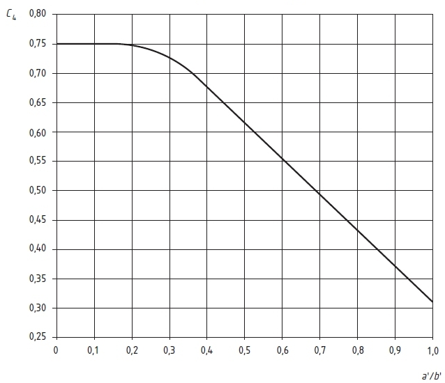
Fig. 10.7-4 – Shape factor C4 for bolted non-circular flat end with narrow-face gasket