Variables
s. Wind load zone
Table NA.B.3 — Simplified velocity pressures for buildings up to 25 m in height
|
Wind zone |
Velocity pressure qp in kN/m² at building height h |
|||
|
h £ 10m |
10 m < h £ 18 m |
18 m < h £ 25 m |
||
|
1 |
Midland |
0,50 |
0,65 |
0,75 |
|
2 |
Midland |
0,65 |
0,80 |
0,90 |
|
Coastal areas and Baltic Sea islands |
0,85 |
1,00 |
1,10 |
|
|
3 |
Midland |
0,80 |
0,95 |
1,10 |
|
Coastal areas and Baltic Sea islands |
1,05 |
1,20 |
1,30 |
|
|
4 |
Midland |
0,95 |
1,15 |
1,30 |
|
Coastal areas of North Sea and Baltic Sea and Baltic Sea islands |
1,25 |
1,40 |
1,55 |
|
|
North Sea islands |
1,40 |
— |
— |
|
s. Terrain categories
s. Snow load zones
Table C.1 — Height above sea level/ Snow load dependencies
|
Climatic region |
Calculation rule |
|
Alpine Region |
|
|
Central East |
|
|
Greece |
|
|
Iberian Peninsula |
|
|
Mediterranean Region |
|
|
Central West |
|
|
Sweden, Finland |
|
|
UK, Ireland |
|
|
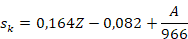
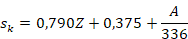
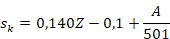
With sk characteristic snow load on ground [kN/m2] A Terrain height above sea level [m] Z Number of zone in map. |
|





s. Snow load zones
s. Annex C from: EN 1993-4-1:2007 + AC:2009 + A1:2017 (D)
Wind pressure distribution around the circumference of circular silos
The distribution of the wind pressure around a flat silo with circular outline or a ground-based tank (see figure C.1) might be of importance for dimensioning the anchorage and for the buckling analysis.
Data provided in EN 1991-1-4 are not detailed enough for certain cases.
The pressure distribution around a singular silo might be described with the circumferential coordinate θ, whereas the origin is at the windward meridian (see figure C.2).
The circumferential function of the pressure distribution (positive, pointed at the inside) of a singular vertical silo with closed roofing (see figure C.2) is:

With dc as diameter of the silo and H as its total height (H/dc is the dimensioning ratio for the complete structure including the supporting construction) (see figure C.1). For silos with H/dc < 0.50 you should use the values for H/dc = 0.50. The pressure distribution should not base on the cylinder height Hc.
The circumferential function of the pressure distribution (positive, pointed at the inside) of a closed silo in a group (see figure C.3) is:

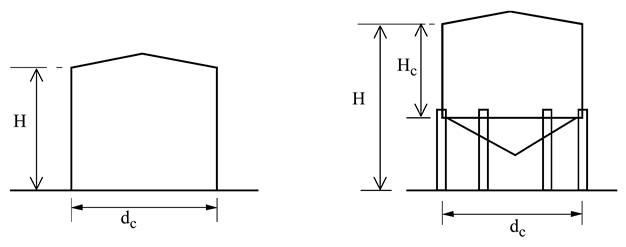
Figure C.1 — Wind-loaded silos
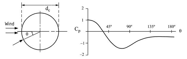
Figure C.2 — Wind pressure distribution over half of the circumference at a
singular vertical silo
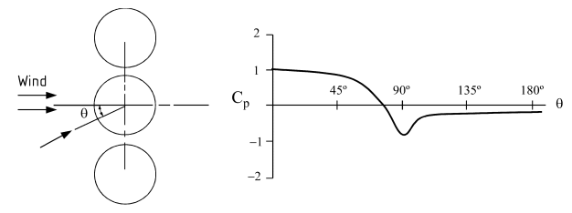
Figure C.3 — Wind pressure distribution over
half of the circumference at a vertical silo in a group
For silos without closed roofing, the following constant pressure factors ΔCp for the inside negative pressure, should be added to the functions above, which increases the pressure pointed at the inside at the windward meridian:
a) Additional inside negative pressure in an silo open at the top: ΔCp = +0.6.
b) Additional inside negative pressure at a vented silo with a small opening: ΔCp = +0.4.
ANNOTATION ΔCp is used as positive pointing at the inside. In this case the resultant of the outside pressure and the inside pressure at the lee side silo wall is approximately zero.
Table 7.14 — Increasing factor κ for circular cylinders in a row
|
a/b |
κ |
|
|
2,5 < a/b < 3,5 |
1,15 |
|
|
3,5 < a/b < 30 |
|
|
|
a/b > 30 |
1,00 |
|
|
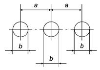
a Distance b Diameter |
||
|
NOTE For a/b < 2,5 the values for the increasing factor κ may be specified in the National Annex. |
||