Module EQU for equation evaluation
Module EQU serves for the calculation of user defined equations. After starting the module, a base editor, advanced editor or table editor can be selected. With the base editor up to 20 variables and 20 equations can be specified. The advanced editor displays 20 or 40 lines, with up to 200 variables and equations. After selection of the table editor a mask appears for the presentation of results and variables for all chapters of a project. In the section option an example can be selected, which explains the functionality of the module.
The base editor provides three comment lines, a variable field and an equation field. In the variable field, variable names can be specified. A comment is allowed left of the variable name, separated by an equation sign = or empty space symbol. Besides the variable field, is the value field of the variable values placed. The functionality is visible in the following example:

The variables Di, P, L, B and Hb are defined, with the corresponding values in the value field at the right side. These values can be used in the equation field. Equations can be written in the equation field. Again, a comment is allowed left from the equation. The variable names #61, #62, …, are also assigned to the equations, additionally to user defined names. The result of the equation appears in blue color at the right of the equation
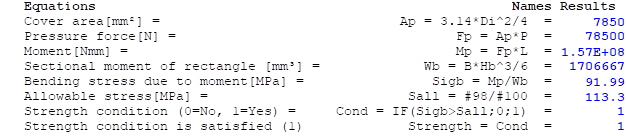
The first line of the equation field shows the equation Ap=3.14*Di^2/4, which gives the value 7850. In the next line, the pressure force Fp=Ap*P is calculated, with the result 7850*10=78500. The equations may contain a comment at the left side, which is separated by an equal sign =. The allowable stress Sall in line 6 is calculated with variables in the material region below Sall=#98/#100.
Units can be converted in the units area:

After specification of the value and unit of variable #121, the selected unit may be changed. If units are not convertible, a message box is displayed.
In the material section two materials A or B can be selected:
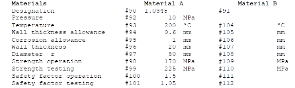
The variables #90-#121 can be used in the equation field. The following options are provided in the option field:
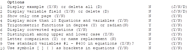
In the case of Y/N values N signifies no and all other values yes. With option 1 the example above can be executed. Option 2 = Y shows only one pate and Option 3 = Y displays 20 lines for variables and 20 lines for values. The variable field can be displayed with option 4 = Y; D deletes the variable field and calculates all values again. Option 5 <> N calculates trigonometric functions in degree. Option 6 allows to display all converted equations, i.e. after replacing all variables. Option 7 is used for upper and lower case of variable names. For functions, upper and lower case are ignored. Option 8 concerns the type of equation conversion. The variable names can be extracted letter by letter from the equation text, always up to the next separation sign, such as: : /*()-+… For Option 8 = N the names are directly replaced, in which variable names and functions are controlled for ambiguity. This option can be changed, of problems arise with equation conversion. For Option 9 = Y the standard variables #1-#400 can be used in equations, e.g.: Sall=#98/#100 in the example above. The variables #41-#60 denote variable values and #61-#80 the equation values. If user defined variables #1 to #400 are used, this option must be deactivated. If Option10 = Y is activated, symbols []{} can be used as brackets. It should be considered, that curly brackets {} can not be used for RTF-printing, because Microsoft Word uses curly brackets for RTF-commands.
Upper and lower case is ignored for functions. The following functions are available:
DLOG, LOG10, ARCCOS, ARCSIN, DEXP, SINH, TANH, ABS, ATN, COS, EXP, LOG, RANDOMIZE, RND, ROUND, SGN, SIN, SQR, TAN, IF, WENN, MAX, MIN
ABS(x) calculates the absolute value of x. In the equations, the absolute value symbol may also be used, e.g.: ABS(-2) = |-2| = 1
ARCCOS, ARCSIN and ATN calculate the inverse trigonometric functions sin-1, cos-1 and tan-1.
COS, SIN, TAN calculate the cosine, sine and tangens.
EXP(x) and DEXP(x) calculate the value e^x, e.g.: EXP(1) = 2.718 = e
DLOG and LOG calculate the natural logarithm, e.g.: DLOG(2.718) = 1
IF calculates conditions with the following syntax:
IF( Condition; Formula(TRUE); Formula(FALSE) ), e.g.: IF( 2>1; 2*2; 4*4) = 4
LOG10 calculates the logarithm to the base of 10, e.g.: LOG(10) = 1
MAX(a;b;c;d) calculates the maximum of several values, e.g. MAX(1;2;3;4) = 4. A semicolon is used as default separation symbol. The number of values is arbitrary.
MIN(a;b;c;d) calculates the minimum, with the same defaults as MAX.
Randomize initialises the random generator
Rnd(x) yields a random number between 0 and 1
Round(x) rounds the number x to an integer value.
SINH and TANH calculate the hyperbolic sine and tangens
SQR calculates the square root, e.g.: SQR(4) = 4^0.5 = 2
WENN is the same as IF.
Individual input masks can be created with module EQU. The method is illustrated for an example with a nozzle in a cylinder. First, module EQU is opened and the variable sP, T, s, Di, Dsa and sa are entered as below:
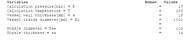
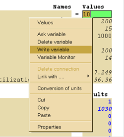
In order to link the pressure P with another module, the context menu is opened with the left mouse key, and write variable is clicked in order to add the variable to the connection watch list, as below:
Subsequently, we open module AD-B1. In module B1 on the input field for the calculation pressure we open the context menu using the right mouse key:
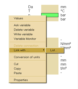
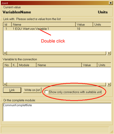
Under the option Link with… the entry List… is selected. In the link window the option Show only connections with suitable unit must be deactivated. Afterwards, in the upper window the variable 1 form module EUQ1 can be selected with a double click for the connection:
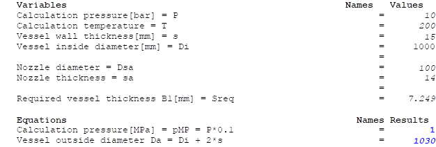
The wall thickness s and the temperature T can be connected in the same way. For the outside diameter, we add the equation Da = Di + 2*s in module EQU:

Another equation pMP = P*0.1 was also entered for the pressure in MPa. As before, the outside diameter can be added to the watch list for connections and be linked with the corresponding variable in module B1.
The material can be entered in the input field for material A of module EQU1 and be linked with the vessel material in Module B1. Finally, the weld factor and other secondary variables are entered in module B1. Thereafter, the required wall thickness is calculated. This can be added to the connection watch list and connected with a variable value in module EQU1. In module 1, the following result may appear:
After this, we open module B9N and pull the module tab 2B1 with fixed mouse key into module B9N, in order to connect module 1 with B9N
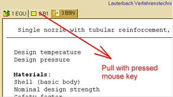
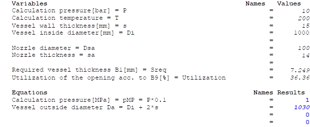
The nozzle diameter and wall thickness in module EQU can be added to the connection watch list and be linked with the corresponding values in module B9N. Material B can also be specified in module EQU and linked with the nozzle material in B9N. Finally, the missing values in module B9N are entered until the utilization is calculated. This can be connected with a variable value in module EQU. The result may be as follows:
The advanced editor contains an equation field with corresponding values. In a line of the equation field, multiple equations and variables can be specified, separated by a colon: . The same rules hold for equations as for the base editor. An example may look as follows:
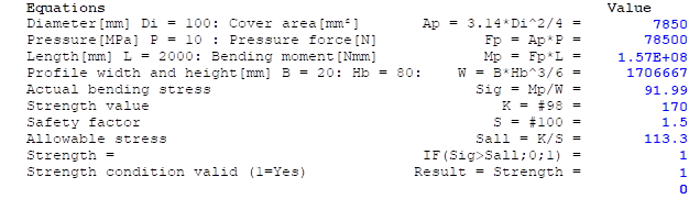
This example can be executed using the option Display example = Y at the end of the of the input mask in the option region.
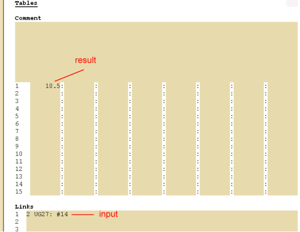
The table editor has a comment region, a table field and a link region. Variables and results from other modules can be listed in the table, e.g. for comparison of required and available wall thicknesses, Stresses, pressure etc. In order to illustrate the functionality, we open a module EQU and an additional module, e.g. UG-27 for cylinders acc. to ASME. Afterwards, we perform a calculation acc. to UG-27. Presentation of the calculation pressure of module UG-27 in the table of module EQU requires the variable number 14 and module number 2 as illustrated in the figure below:
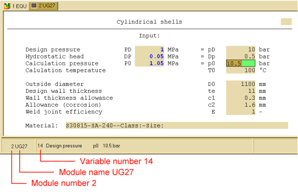
We move to module EQU and enter in the first line of the link region the module number, module name, a colon and the variable number:
2 UG27 : #I4
Each line of the link region is assigned to a corresponding line of the table region. The module number at beginning of the line is required for the calculation of the value of variables from module 2. The module name UG27 is used for control. After the colon the variable number #14 is inserted, identified by the letter #. In module EQU appears the value #14 in the first line of the table, as in the figure below:
We can insert a predefined link line, entering the letter Y in the line Execute example of the Option region as below:

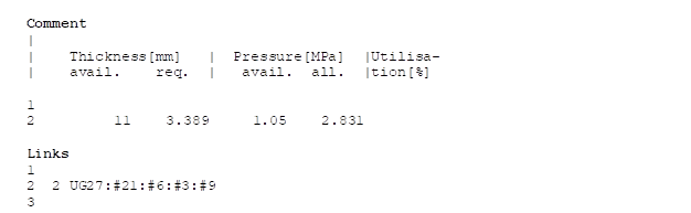
In the second line of the links the following variables are automatically inserted:
2 UG27:#21:#6: #3:#9
The number 2 identifies the module name, followed by the module name UG27 for control. Additional columns of the table are separated by a colon. In the table region the available and required thicknesses as well as the final and allowable pressure in MPa are shown, e.g.:
Form for equations (test version)
The option link variables links variables directly with the corresponding modules, which actualises calculation results immediately. It is possible to insert equations between colons. A line for module S31 may look as follows:
2 S31:#16::#4/10::Max(#lll;#112)/#113* 100:
UTLN1=MAX(#95;#96;#97;#98)/#102*100: UTLN2=MAX(|#98|;|#99|)/#103*100: Max(UTLNl;UTLN2)
The equation : UTLN2=MAX(|#98|;|#99|)/#103*100: calculates the utilisation in %, where the variables #98 and #99 denote the membrane stress and #103 the allowable stress. The result is assigned to variable UTLN2 and can be used in other formulas, e.g.:
Max(UTLN1;UTLN2)
Variables from different modules can also be used in a link line, by specification of the module number, e.g. : #4(3)/10: In this example variable number 4 from module 3 is used.
For a project with multiple modules the table editor EQU can be called and the example executed. Afterwards, the result from the modules is listed in a table. This table can now be modified as necessary. The columns of a link line are always separated by a colon and are assigned to a corresponding column in the table region. The first column of a link line specifies the module and is not displayed in the table.
In a column of a link line user defined equations can be inserted also, e.g. : alfa = ArcCos(#21(2)/#24(2)) : calculates the arccosine of variable 21 from module 2 divided by variable 24, which is in UG27 wall thickness / diameter. The user defined variable alfa can be used in other equations. Further, a value can be assigned to a variable of another module, e.g. : #21(2) = 1220 : Variable 21 is assigned the value 1220 in this example. In order to update calculation results, module change may be required, whereas linked variables are immediately updated (Option link variables).
1. The user defined variable fields and equation fields are identical for multiple EQU modules. They can be deleted in the Option region. When variables of module EQU are required in additional EQU-modules, the values can directly be evaluated using Standard variable numbers. As example, the variable values #41-#60 of the base editor and the equation values #61-#80 can be evaluated using the module number, as #41(2) with module number 2 for the first variable. If user defined variables are used in multiple EQU modules, these modules must be executed in the correct order at program Start, in order to avoid missing variables. Eventually the single modules must be called repeatedly.
2. Variable names and equations may include a remark at the beginning, separated by an equal sign = or a space symbol as separation symbol.
3. For (Y/N) input values holds N=No, all other values signify Yes.
4. The Option trigonometric functions in degrees is eventually not useful for nested functions as Cos(Sin(30), because the internal conversion factor from degree to radian is multiply inserted for Sin(30*Pi/180) and additionally for Cos(Pi/180*Sin(30*Pi/180)). Such equations are usually evaluated in radian.
5. User defined variables should not contain function names or Standard variables VI to #400. If user defined variables #1-#400 are used anyway, the corresponding Option use Standard variables #1-#400 ... should be deactivated (N).
6. Multiple declarations should be avoided, as: a=10: b=2*a: a=100: d= 3 * a:. In this case the last value is used for the evaluation, with the result: a=l 0 : b=2 0 : a=100: d=300. For multiple declarations in following lines the last value is used. Older equations can be recalculated with function key F7, where the actual last value is used for the first equations, until a new declaration is given. Therefore, this notation is unclear.
7. Error test: The bracket number is not checked. If too few or to many brackets are used, the equation is evaluated up to the first error, without further messages. For other writing errors the equation is also evaluated up to the first error. In the case of division by zero the evaluation is terminated and the last value displayed, e.g. 1/0 gives 1. A message appears only if variable names are missing.
8. Curly brackets {} should not be used, because Microsoft uses curly brackets for RTF-commands when it is printed as RTF-file. After opening such a document, an error message may appear, that Microsoft-Word cannot read this document.
Several options have already been explained in the first section on the base editor.
11. Show material properties (Y/N) omits the material data using N.
12. Separation symbol for IF-equations (Standard;) changes the Separation symbol for the IF, Max(a;b) and Min(a;b) functions. Changing this values should avoid overlapping with other Symbols, as dot, comma, brackets, comment sign ('), Separation sign for equations (:) etc.
13. Comment sign (default'), changing should consider the remarks for Separation symbol above.
14. Recalculate only actual equation after changes holds for the advanced editor and means the for Y only the equation line is recalculated, which was actually modified. The input N calculates all equations in the following lines. For a total calculation the function key F7 can be used.
15. Display variable field (default N): Input Y displays a message box with user defined variable names and values. Equations are not displayed.
16. Display equation field (default N): Input Y displays a message box with user defined variables, equations and calculated values.
17. Link variables to corresponding modules (default N). Input Y links the table values with the corresponding variables in the link field, e.g. VI (2) links variable l in module 2 directly, when this module exists. If an equation appears in the corresponding link line, the link is not established.
18. Stop calculation (Y/N): Specification Y performs no calculations. When typing errors occur, the calculation can be interrupted anytime hiting the ESC key. At the same time, the option Stop calculation is set to Y. After correction of the equations this option can be reset to N.
19. Symbol for standard variables (default #): The default symbol for standard variables of the actual module is #, e.g. #98 for the strength value of material A in module EQU. The module name can be added in brackets for values of variables of other modules, e.g. #98(2) for the value of variable number 98 from module 2. When this symbol is changed, no letters, numbers or bracket symbols should be used, because confusion with user defined variables may occur. As alternative to # the symbols @, _, ~ , °, ˆ are allowable.