Calculation of heat exchanger networks
All heat exchangers that you want to connect in a network must first be thermally designed with the LV program WTS (shell and tube heat exchanger) or AC (cross-flow heat exchanger) and saved as an .atl file.
>> See WTS or AC manual.
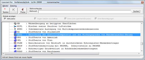
Start the NETZ module in treeview
|
|
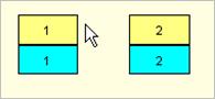
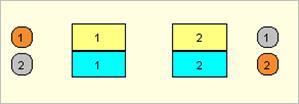
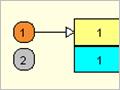
In the tubes (yellow) |
|
|
Around the tubes (blue) |
|
|
Entrance (orange) |
|
|
Exit (gray) |


The "Plan network" button takes you to the graphical interface to plan the heat exchanger network.
First define up to max. 10 heat exchangers for your network.
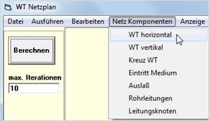
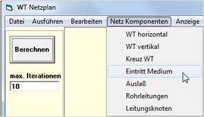
NetComponents -> WT Horizontal/vertical
Use "left mouse button and drag" to create a graphical symbol for each transformer.
Set medium inlet and outlet
Now set inlet and outlet for the media. Inlet is displayed in orange, outlet in gray.
Create pipe connections
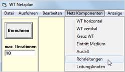
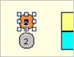
Pipes can only be created from an entry node. To do this, select the center of the symbol until your mouse pointer turns into a black arrow and drag the pipe connection to your exchanger while holding down the left mouse button. Interconnect your complete network this way.
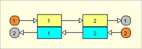
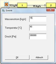
Double-click on the inlet node to open a dialog box where you can enter the mass flow, temperature and pressure at the inlet. The mass flows are displayed.
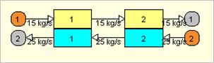
Double-click on the exchanger to set the exchanger data
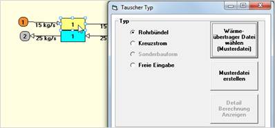
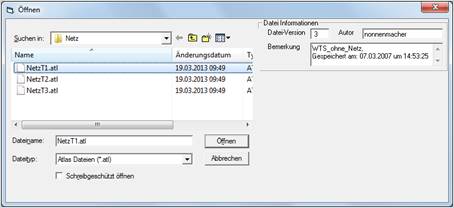
Select an already created ATL file (exchanger already thermally designed). As soon as all exchangers are defined you can start a calculation. The temperature distribution is displayed.
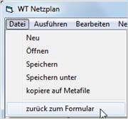
Via "File / back to form" you switch back to the LV module NETZ.
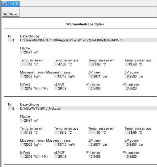
Here you get all important data of your heat exchanger network clearly presented. The data can be printed out for documentation purposes.
Double-click on a heat exchanger:
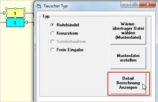
The program switches to the WTS module and displays the thermal design of the transformer.
Here you can change all data as you wish (see WTS manual).
Press STOP to switch back to the network!
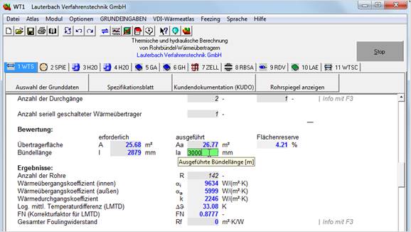
After a change, the mesh must be recalculated via the Calculate button!
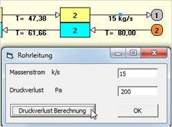
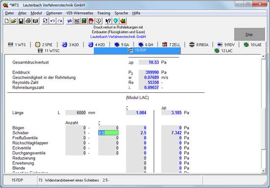
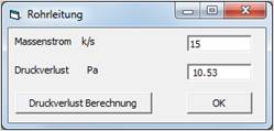
By double-clicking on a pipeline, you can enter known pressure losses directly or perform a pressure loss calculation with the FDP module. Button: Pressure loss calculation
Under 'Save file' the network can be saved as a .net file for further processing at a later time.
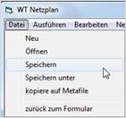

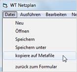
Under "File / copy to Metafile" the network can be saved as a graphic (WMF.file) and inserted into other applications.