Operation of the program
Start VERD by ‘Programs’ / ‘Heat‘ / ‘VERD – Shell and Tube Vaporizers’.
|
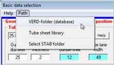
In this menu you can determine the network paths for a network installation of VERD, the VERD basic data (tubes, pitches, shells), the tubesheet library and the properties module ‘STAB’. |
|
After starting the program, the ‘Basic data selection’ dialog box appears. In this dialog box, you can specify company standards or variables of series and media included in the module. The conception of the VERD program is that only few mouse clicks are needed to select type and basic design of the heat exchanger as well as tube-side and shell-side medium. Only few values (temperatures, pressures, mass flows, heat duty) have to be entered to generate a tubesheet ready for construction and to design a heat exchanger.
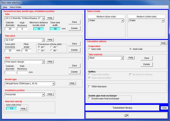
Before starting the calculation, the type and the general layout should be known if possible. To specify this, the ‘Basic data selection’ dialog box is provided. Furthermore, default values for tube dimensions and shell dimensions can be used to meet the requirements of construction series or company standards for design of the heat exchanger.
The following basic data can be selected:
|
Description |
Contents |
Entry (example) |
Meaning |
|
|
Tube dimensions |
List of tubes used by the designer |
25 x 2, Shell-Bu. 12 Bend R 37 |
Tube outside diameter |
25 mm
|
|
Wall thickness |
2 mm |
|||
|
Bundle-shell distance (BS) |
12 mm
|
|||
|
Bending radius |
37 mm |
|||
|
Pass lane width |
49 mm |
|||
|
Tube pitch |
Selection of tube pitch |
32 x 60 ° |
Crosswise distance |
32 mm |
|
Pitch angle |
60 ° |
|||
|
Shell dimensions |
List of shells used by the producer |
88.9 x 3.2 Dist. Baffles 50 |
Shell outside diameter
|
88.9 mm |
|
Wall thickness |
3.2 mm |
|||
|
Min. baffle pitch |
50.0 mm |
|||
|
Bundle type |
Rear end head types |
Straight tube, U-tube, Floating head (split-ring), Floating head (outside packed), Floating head (pull-through) |
||
|
Installation position |
|
Horizontal Vertically upwards Vertically downwards |
|
|
|
Tube-side velocity |
|
Desired velocity [m/s] |
||
|
Shell-side velocity |
|
Desired velocity [m/s] |
||
|
Tube-side medium |
Properties |
Water |
|
|
|
Shell-side medium |
Properties |
Water |
|
|
Several standard tubes according to DIN standards are given.
The description 25 x 2, Shell-Bu. 12, Bend R 37 means:
· Tube outside diameter 25 mm
· Wall thickness 2 mm
· Minimum distance bundle-shell 12 mm. This distance is not underrun when the shell is completely tubed. This value can be modified in the input mask during the design process. If you have selected 'TEMA Standard' in the 'Selection of basic data', the minimum bundle-shell distance is calculated according to TEMA and cannot be overwritten anymore. If you want to change the value, you have to deactivate the 'TEMA standard' option in the 'Selection of basic data' first.
· Bending radius for U-tube 37 mm
The description refers to the smallest bending radius possible. The tube outside diameter, the wall thickness and the tube material essentially determine this radius.
Bending radii for some tubes made from C steel and CrNi steels
|
Tube outside diameter |
Smallest bending radius for U-tubes with the wall thickness s [mm] |
||||
|
s = 1.2 |
1.6 |
2.0 |
2.6 |
3.2 |
|
|
16 |
30 |
24 |
20 |
- |
- |
|
20 |
47 |
34 |
26 |
23 |
- |
|
25 |
- |
51 |
37 |
35 |
27 |
|
30 |
- |
62 |
42 |
38 |
35 |
|
38 |
- |
- |
52 |
47 |
42 |
If the tubes closest to the exchanger center are bent crosswise or the passes are separated by separating baffles in the bonnets you should enter the pass lane width instead of the bending radius.
The pass lane width is the clearance between the tubes of two passes. The bending radius calculates the pass lane width:
Pass lane width = 2 x bending radius - tube outside diameter
Bending radius or pass lane width are only required for two or multiple tube side passes.
Distance and arrangement of tubes in the tube bundle.
The crosswise pitch, the longitudinal pitch and the pitch angle determine the arrangement of the tubes in the tube bundle.
The crosswise tube pitch is the center-to-center distance of two adjacent tubes in a tube row, crosswise to the flow direction. The longitudinal tube pitch is the center-to-center distance of two adjacent tubes in flow direction.
Crosswise and longitudinal pitch are depending from the pitch angle. There are four frequently used tube pitches. The most frequently used pitch is the 60° tube pitch.
32 x 60° means:
Crosswise tube pitch 32 mm
Pitch angle 60°
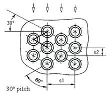
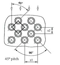
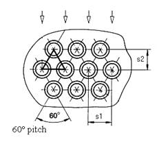
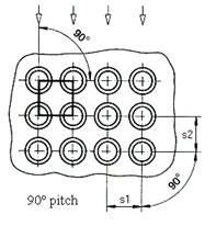
a) Triangle pitches 60° and 30°
With the triangle pitches, you can achieve the highest tube density in the shell. This means, that in a shell with a triangle tube pitch there can be 15% more tubes than in a shell with a square tube pitch. Additionally, with triangle pitches the heat transfer is better than with square pitches. This means the same area has a better thermal performance than with a square tube pitch.
Disadvantages of triangle pitches:
No mechanical cleansing of the outer side of the tubes is possible and the pressure drop is higher than with square pitches.
b) Square pitches 45° and 90°
A square pitch should be used for all heat exchangers with expected greater shell-side fouling.
The 45° pitch leads to a better heat transfer with laminar flow due to better turbulences. If the pressure drop is the limiting element of the heat exchanger, the 90° pitch should be used for turbulent flow.
Conversion of pitches
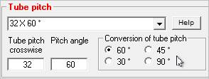
With the 60° pitch, the crosswise tube pitch should be about 1.25 to 1.5 times the tube outside diameter.
By means of using the 'conversion of tube pitch' the crosswise pitch of the according 30°, 45° und 90° pitch can be calculated.
Under shell diameter numerous shells are predefined in accordance to DIN standards 2448 and 2458 for seamless and welded tubes.
273 x 6.3 Dist. Baffles 100 means:
· Outside shell diameter = 273 mm
· Wall thickness = 6.3 mm
· Minimum baffle pitch = 100 mm. This pitch is not underrun when the heat exchanger is designed. While the calculation is running this value can be modified in the input mask afterwards.
>> The minimum baffle pitch should not underrun 20% of the inside diameter of the shell, but be at least 50 mm.
If you have chosen ‘Free input / design’ for the shell the program automatically selects a shell from the list of shells during calculation of the heat exchanger. The selection criteria is the desired flow velocity in the tubes. The program considers not exceeding the desired velocity in the tubes when the shell is tubed completely. The desired velocity is an upper limit for the velocity in the tubes.
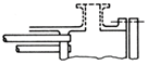
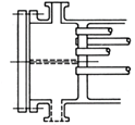
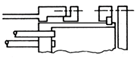
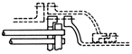
With specifying the bundle type you specify the design of the tube-side head. Together with the option ‘Tema standard’ the calculation of the tubesheet is adjusted to the values of TEMA standard.
|
Front End |
Shell |
Rear End |
||||
|
A |
|
E |
|
L |
|
|
|
Channel and Removable Cover |
One Pass Shell |
Fixed
Tubesheet |
||||
|
B |
|
F |
|
M |
|
|
|
Bonnet (Integral Cover) |
Two
Pass Shell |
Fixed
Tubesheet |
||||
|
C |
Removable Tube Bundle Only |
|
|
N |
|
|
|
Channel Integral with Tube-Sheet and Removable Cover |
Fixed
Tubesheet |
|||||
|
N |
|
P |
|
|||
|
Channel Integral with Tube-Sheet and Removable Cover |
Outside Packed Floating Head |
|||||
|
|
S |
|
||||
|
Floating Head With Backing Device |
||||||
|
T |
|
|||||
|
Pull Through Floating Head |
||||||
|
|
U |
|
||||
|
U-Tube Bundle |
||||||
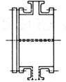
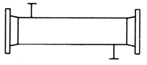
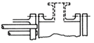
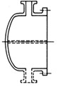
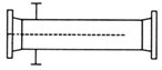
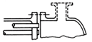
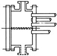
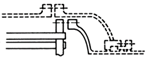
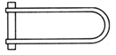
The installation position is important only for condensation processes because due to the type of installation of the heat exchanger different correlations have to be used for the thermal calculation.
The desired velocity in the tubes determines the selection of the shell diameter if ‘Free input / design’ has been chosen under shell diameter.
The program tries not to exceed the desired tube-side velocity and selects an appropriate shell from the list of shells under ‘shell diameter’.
If a shell has been selected under ‘shell diameter’ the tube-side velocity is fixed so that indicating a desired tube-side velocity makes no sense and is therefore deactivated.
The user can modify the value for the desired tube-side velocity at any time by clicking the input field.
Typical values for tube-side velocity:
|
Medium |
Velocity [m/s] |
|
Water |
1.5 – 2.5 |
|
Heavy hydrocarbons |
0.5 – 1.0 |
|
Gases 1bar |
20 - 30 |
|
Gases 70 bar |
5 - 10 |
|
Gases in vacuum |
Up to 70 |
|
Material |
Max. flow velocity of cooling water |
|
SF-Cu |
1.4 |
|
Cu Zn 28 Sn |
1.8 |
|
Cu Zn 20 Al |
2.2 |
|
Cu Ni 30 Fe |
3.0 |
|
Cr Ni - Steels |
3.5 |
|
C - Steels |
3.5 |
(From: Walter Wagner, Wärmeübertrager)
The velocity is limited due to cavitation and erosion. To avoid erosion at the inlet and outlet region, the product ρ · v² should also be put into consideration. This dynamic pressure considers also the influence of the fluid mass.
The tube-side product ρ · v² for liquids should not exceed 9000 kg/(m·s²).
The desired shell-side velocity serves for determination of the distance of the segmental baffles. If the option ‘Tema standard‘ has been selected the resulting value is checked according to Tema standard and corrected if necessary.
The user can modify the value for the desired velocity in the tubes at any time by clicking the input field.
Typical values for shell-side velocity:
|
Medium |
Velocity [m/s] |
|
Water |
1.0 - 1.5 |
|
Heavy hydrocarbons |
0.5 - 1.0 |
|
Gases 1bar |
20 - 30 |
|
Gases 70 bar |
5 - 10 |
|
Gases in vacuum |
Up to 70 |
The velocity is limited due to vibration, cavitation and erosion.
The velocity is limited due to cavitation and erosion. To avoid erosion at the inlet and outlet region, the product ρ · v² should also be put into consideration. This dynamic pressure considers also the influence of the fluid mass.
|
Maximum values of the product ρ·v² [kg/((m·s)²] shell side |
|||
|
Shell side inlet |
Without impingement plate |
Non-erosive and non-corrosive single-phase fluids |
< 2250 1) |
|
All other liquids including a liquid at its boiling point |
< 750 1) |
||
|
With impingement plate |
|
< 6000 2) |
|
|
Shell side outlet |
|
|
< 6000 2) |
1) Velocity means velocity in nozzle
2) Velocity means velocity in first tube row
For all other gases and vapors, including all nominally saturated vapors and for liquid vapor mixtures, impingement protection is required.
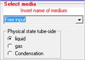
The tube-side and shell-side media is selected by using the pull-down-menu. The physical state of the media ‘liquid or gas’ which is important for calculation of the heat transfer is set automatically. The values for the desired tube-side and shell-side velocities are adjusted to the physical state.
If ‘Free input’, ‘Proper’ and ‘STAB’ (property tables created by the user) have been selected the physical state has to be indicated by the user. Then, the values for the desired tube-side and shell-side velocities are adjusted to the physical state.
If ‘Free input’ has been selected the properties have to be entered manually (see section ‘Manual input of properties - ‘Free Input’‘).
The basic VERD package provides several property modules for single substances:
|
Water |
Air |
NH3 / NH3 condensation |
|
Sea water |
Natural gas L and H |
Typical oils (OEL) |
|
Saturated steam (condensation) |
Natural gas (free input) |
Thermal oils (TOIL) |
|
Glycol-water mixtures |
Flue gas |
Refrigerants |
|
Free input |
|
|
This list can be extended by further property modules which are not included in the basic package. You can also integrate our properties program PROPER (not included in the basic package) which comprises a data base with more than 700 substances. PROPER provides properties of pure substances and mixtures. Furthermore, the free input of properties is possible with the SDAT module. If both media have been preselected with the menu item ‘Basic data’ the properties are calculated automatically by the corresponding modules (e.g. water, air, natural gas).
With shell-side evaporation (pool boiling) the material data of the evaporator tubes are considered by using the heat penetration coefficient b.
With tube-side evaporation (nucleate boiling in pipe flow) the material data of the evaporator tubes are not required.
In the selection box for the tube material the following properties of some common tube materials are included:
|
λ |
Thermal conductivity [W/(m·K)] |
|
ρ |
Density [kg/m³] |
|
cp |
Specific heat capacity [J/(kg·K)] |
If you want to use tubes made of other materials select ‘Free input’. In this case you have to enter the properties of the tube in the VERD input mask.
The tube material can be changed at any time in the VERD input mask. (see: Tube material
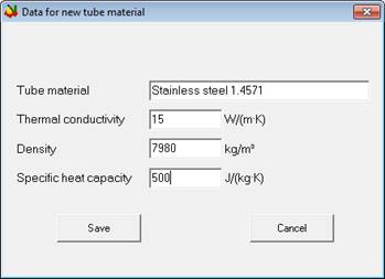
You may also enter your own tube material data. Select ‘Save tube material’ to create a new data record.
Now enter name, thermal conductivity [W/(m*K)], density [kg/m³] and specific heat capacity [J/(kg*K)]. The data are available in the program as soon as you have pressed the ‘save’ button.
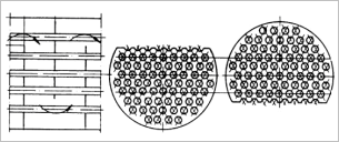
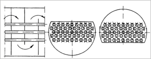
By default WTS calculates segmental baffles. The window size should range from 15% to 40% of the shell diameter.
|
Segmental baffles when completely tubed
|
|
|
Segmental baffles when partially tubed (No tubes in window)
|
|
Baffle spacing
The meet the requirements of the desired shell-side flow velocity of the medium, the program calculates the baffle spacing. At the beginning, the inlet baffle spacing is set equal to the baffle spacing (see Give inlet baffle spacing).
You can adjust the baffle spacing in the KOND input mask.
The option 'No-tubes-in-window' creates a tubesheet without tubes in the window zones (see Segmental baffles).
Application:
·
Avoiding of tube vibrations.
The unsupported tube length is reduced to the baffle distance. The unsupported
tube length in the window zone is twice the baffle distance
· Significant reduction of pressure drop in window zones
With this option you can design multi-tube heat exchangers (without baffles). In contrast to a double pipe heat exchanger, consisting of one outer and one inner tube, a tube bundle is assumed with the option ‘Shell without baffles’!
The option ‘TEMA Standard’ ensures that the dimensions specified according to TEMA are kept in the calculation. The TEMA module is activated automatically and dimensions according to the TEMA code appear in the VERD user interface. For example, by selecting the bundle type the bundle-shell distance is determined according to the TEMA code.
With the option ‘Double-pipe heat exchanger’ a heat exchanger consisting of an internal and an external tube can be calculated. The internal tube and the pipe can be selected in a selection box on the left hand side of the basic data selection. The values can be changed in the VERD input mask at any time.
With the button ‘Tubesheet library‘ the values of a tube area created by yourself can be transferred from your tubesheet library into the menu item ‘Basic data‘. After pressing this button a table is displayed where you have to mark the selected tubesheet by mouse-click.
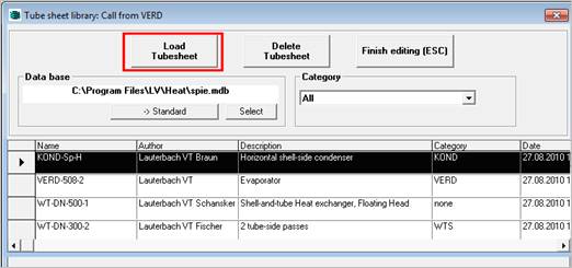
To transfer the values of the tubesheet click ‘Load tubesheet’. With ‘Finish editing (ESC)’ you return to the ‘Basic data‘ menu. The data transfer overwrites possibly entered diameters of tube and shell.
>> Please note that creating, editing and saving of the tubesheet in the tubesheet library is only possible in the SPIE module.
After selection of basic data is completed, confirm your selection by ‘OK’. The next selection box appears:
Select number and arrangement of the tube-side passes by clicking on the respective button.
You can also specify the system data (temperatures, pressures, mass flows), but these values can also be entered in the VERD mask at a later point of time.
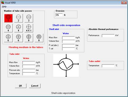
Selection of number of tube-side passes and bundle type.
|
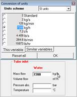
TIP: Conversion of units A mouse click on the unit or a double click on the input field activates the conversion of units. Enter the values in the unit you have at hand; e.g., mass flow in kg/h. The value is immediately converted in all other displayed units. The unit with the activated ckeckbox is displayed on the mask and will be used for the documentation. Please confirm your input with ‘OK'. |
|
On the VERD user interface the user controls the run of the calculation. From here you can switch to any other module.
The VERD user interface contains all input variables required to calculate a heat exchanger. These input values also appear in the input masks of the selected chapters. They can be entered or modified there as well because all chapters are linked with each other.
To switch to the user interfaces of the single modules click the ‘ATLAS’ menu and the menu item ‘Chapter’ (see manual of the ATLAS program system).
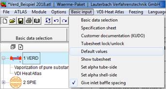
VERD provides a special menu for basic inputs which is in the menu bar of the input mask.
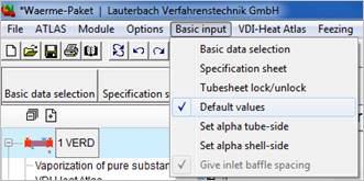
Input mask and ‘Basic input’ menu
With this menu item you return to the ‘Selection of basic data‘ dialog box. There you can modify the tube dimensions or the tube pitch or select a new shell.
For output of specification sheets to MS EXCEL click the menu item ‘Specification sheet’. MS EXCEL has to be installed before activating this item.
You can choose between German, English or French in the 'Language' menu.
The KUDO module creates an abridged documentation with the performance characteristics and only a few geometrical data like outside diameter of the shell and tube length. Geometrical data documentation is reduced to only a few data like e.g. outside diameter of the shell and tube length.
If a tubesheet is loaded from the tubesheet library it is always locked, i.e. the geometrical variables of the heat exchanger are fixed and it can be neither overwritten in the input mask nor recalculated by the program. If you want to modify these variables, click the menu item ‘Tubesheet lock / unlock’ to unlock the tubesheet for editing.
The ‘Default values’ are activated if this menu item is ticked. Click ‘Default values’ to deactivate the option or to re-activate it.
If the option is activated VERD uses default shells for the design of the heat exchanger. For example, if the user enters a new number of tubes during the optimization, VERD selects the shell which just has enough space for this number of tubes.
If the option is deactivated and a new number of tubes is entered, VERD calculates the exact inside shell diameter resulting from this number of tubes.
If the option is activated again, the heat exchanger is automatically recalculated. VERD uses again default dimensions.
The tubesheet is displayed in the graphics window. Changes in the input mask are presented in the graphics dynamically.
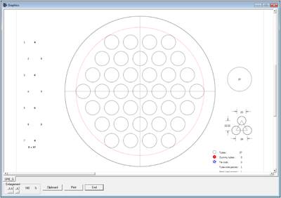
If the heat transfer coefficient in the tubes (alpha i) is known from other sources (such as measurements) and therefore doesn't need to be calculated by VERD, this value can be entered into the field ‘Heat transfer coefficient (inside)’ on the VERD input mask after clicking the option ‘Set alpha tube-side’. In this case the user interface ‘Clear value of variable’ is not displayed, i.e. no recalculation to a dependent variable like e.g. the tube diameter, the number of tubes, the flow velocity etc. is done. If you click the option ‘Set alpha tube-side’ again the heat transfer coefficient in the tubes is calculated by VERD.
If the heat transfer coefficient around the tubes (alpha a) is known from other sources (such as measurements) and therefore doesn't need to be calculated by VERD, this value can be entered into the field ‘Heat transfer coefficient (outside)’ on the VERD input mask after clicking the option ‘Set alpha shell-side’. In this case the user interface ‘Clear value of variable’ is not displayed, i.e. no recalculation to a dependent variable like e.g. the distance between the baffles, the number of baffles etc. is done. If you click the option ‘Set alpha shell-side’ again the heat transfer coefficient around the tubes is calculated by VERD.
Before entering the shell nozzle the inlet baffle spacing is set equal to the baffle spacing. After having entered the nozzle diameters the program checks if the distance tubesheet to first baffle is greater than the nozzle diameter plus a run-out length depending on nozzle diameter and shell diameter. If this is the case, the inlet baffle spacing is increased automatically.
Thus you can avoid that the first or the last baffle is below the inlet or outlet nozzle. The increase of the distance is considered for calculating the heat transfer coefficient. This may result in a correction of the required length or of the overdesign (see Rating by overdesign).
You can also enter the inlet baffle spacing as long as it is greater than the baffle spacing or greater than the nozzle diameter plus run-out length. Smaller values are not accepted by default!
If you activate the option ‚Give inlet spacing‘, every positive value is accepted even if it is smaller than the nozzle diameter. Then, the baffle spacing is always calculated and cannot be entered (the input field is locked). The baffle spacing can then be changed by entering the number of baffles.
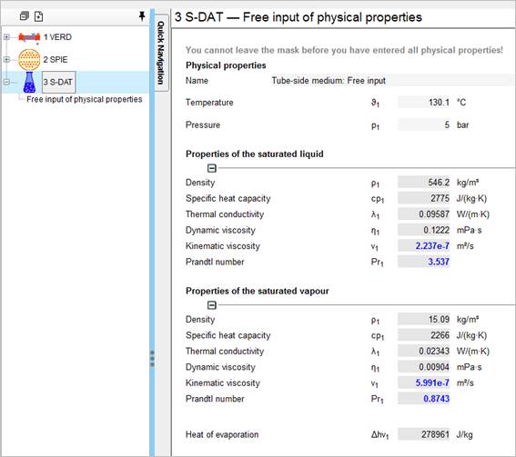
If ‘Free input‘ has been selected in ‘Basic data‘ for one of the media, the properties of this medium have to be entered manually. This is possible with the SDAT module.
After entering the inlet and outlet temperature and the pressure on the VERD mask the SDAT module is activated. Pressure and mean temperature have already been transferred.
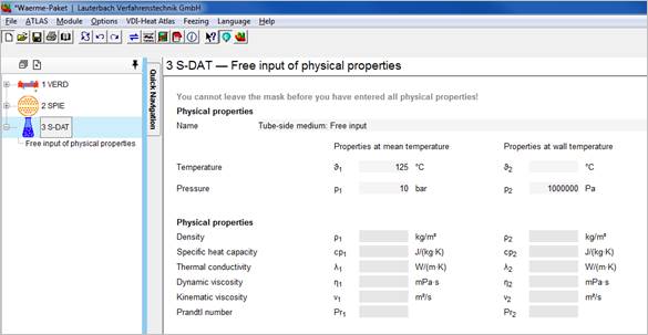
Required data:
· Liquids and gases (single-phase media)
For calculating the heat transfer and the pressure drop, properties at mean temperature and at wall temperature are required. At first start of SDAT the wall temperature is unknown. Please enter only the properties at mean temperature at first. As soon as the data input is complete, the program switches automatically back to the VERD mask. After the wall temperature has been calculated please switch to the SDAT module by clicking on the according tab strip and complete the properties at wall temperature. If you do not enter the properties at wall temperature, the values are replaced by the values at mean temperature for calculating the pressure drop and the heat transfer. Then the accuracy of the calculation decreases. Especially with viscous media like oils greater errors might occur.
· Vaporization of pure substances
When vaporizing pure substances, the properties of the vapor and the properties of the liquid at boiling temperature as well as the critical pressure and the molar mass are required.
· Condensation of pure substances
When condensing pure substances, the properties of the vapor and the properties of the condensate at condensation temperature are required.
As soon as the data input is complete, the program switches automatically back to the VERD mask.
If you have selected ‘Free input’ for both exchanger sides two SDAT modules are created.
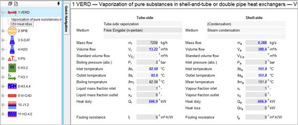 Heat balance
The first value block contains the information about the quantities, pressures and temperatures of both media.
Start your data input on the 'evaporation' side of the input mask. It is necessary to specify either the pressure (boiling pressure) or the mean temperature (boiling point) of the medium to be evaporated. The program calculates the corresponding value in the vapor pressure curve (boiling point or boiling pressure). The inlet and the outlet temperature is set to a value 0,1 °C less or more than the mean temperature (boiling temperature).
Fouling resistances for water in shell and tube heat exchangers (m²K/W)
|
Temperature of heating medium |
Up to 120°C |
120–200°C |
||
|
Temperature of water |
50°C |
Over 50°C |
||
|
|
Flow velocity |
Flow velocity |
||
|
Cooling water |
≤ 1 m/s |
> 1 m/s |
≤ 1 m/s |
> 1 m/s |
|
Seawater |
0.00009 |
0.00009 |
0.00018 |
0.00018 |
|
Brackish water |
0.00035 |
0.00018 |
0.00053 |
0.00035 |
|
Cooling tower and artificial spray pond: |
|
|
|
|
|
Treated make up |
0.00018 |
0.00018 |
0.00035 |
0.00035 |
|
Untreated |
0.00053 |
0.00053 |
0.00090 |
0.00075 |
|
City or well water |
0.00018 |
0.00018 |
0.00035 |
0.00035 |
|
River water: |
|
|
|
|
|
Clean |
0.00035 |
0.00018 |
0.00053 |
0.00035 |
|
Normal |
0.00053 |
0.00035 |
0.00070 |
0.00053 |
|
Sewer |
0.00141 |
0.00090 |
0.00175 |
0.00141 |
|
Muddy or silty water |
0.00053 |
0.00035 |
0.00075 |
0.00053 |
|
Hard (over 250 ppm) |
0.00053 |
0.00053 |
0.00090 |
0.00090 |
|
Engine jacket |
0.00018 |
0.00018 |
0.00018 |
0.00018 |
|
Distilled or closed circle |
0.00009 |
0.00009 |
0.00009 |
0.00009 |
|
Treated boiler feedwater |
0.00018 |
0.00009 |
0.00018 |
0.00018 |
|
Boiler blowdown |
0.00035 |
0.00035 |
0.00035 |
0.00035 |
|
Cooling water |
Fouling resistance |
|||
|
Quench water |
0.00045 |
|||
|
Polyphosphate treatment |
0.00015 |
|||
|
Acid treatment |
0.00008 |
|||
|
Cold brine |
0.0002–0.00033 |
|||
|
Aqueous salt solutions |
0.0002–0.00033 |
|||
© Springer Verlag Berlin Heidelberg 2013
|
TEMA fouling resistances for oil refinery streams in shell-and-tube exchangers (m²K/W) |
|
|
Crude oil and vacuum unit |
|
|
a) gaseous |
|
|
Vacuum overhead vapors Atmospheric tower overhead vapors Light Naphtha |
0.00035 0.00018 0.00018 |
|
b) liquid Crude oil (desalted at 120°C. tube side velocity > 1.3 m/s) |
|
|
T < 120°C |
0.00035 – 0.0007 |
|
120°C <T < 175°C |
0.00053 – 0.0007 |
|
175°C < T < 230°C |
0.00070 – 0.00088 |
|
230°C < T |
0.00088 – 0.0011 |
|
Light gasoline |
0.00018 |
|
Kerosene |
0.00035 |
|
Heavy gas oil |
0.00035 – 0.00053 |
|
Gasoline |
0.00035 – 0.00053 |
|
Light gas oil |
0.00053 – 0.00088 |
|
Heavy fuel oils |
0.00088 – 0.0012 |
|
Vacuum tower bottoms |
0.0018 |
|
Atmosphere tower bottoms |
0.0012 |
|
Cracking and Coking |
|
|
Bottoms Slurry Oil (u>1.5 m/s) |
0.00053 |
|
Light Cycle Oil |
0.00035–0.00053 |
|
Light Coker Gas Oil |
0.00053–0.0007 |
|
Low-boiling liquid products |
0.00053 |
|
Overhead vapors |
0.00035 |
|
Heavy cycle oil |
0.00053–0.0007 |
|
Heavy Coker Gas Oil |
0.0007–0.00088 |
|
Catalytic Reforming, Hydrocracking and Hydrodesulfurization |
|
|
Reformer Charge |
0.00027 |
|
Reformer Effluent |
0.00027 |
|
Hydrocracker Charge and Effluent |
≥ 0.00035 |
|
Hydrodesulfurization Charge and Effluent |
≥ 0.00035 |
|
Recycle Gas |
0.00018 |
|
Overhead vapors |
0.00018 |
|
Liquid product spec. weight > 50°API |
0.00018 |
|
Liquid product 30°API-50°API |
0.00035 |
|
TEMA fouling resistances for oil refinery streams in shell-and-tube exchangers (m²K/W) |
|
|
Light Ends Processing Streams |
|
|
Overhead vapors and gases |
0.00018 |
|
Liquid products |
0.00018 |
|
Alkylation Trace Acid Systems |
0.00035 |
|
Absorption Oils |
0.00035–0.00053 |
|
Reboiler Streams |
0.00035–0.00053 |
|
Visbreaker |
|
|
Overhead vapor |
0.00053 |
|
Visbreaker bottoms |
0.00176 |
|
Catalytic Hydro Desulfurizer |
|
|
Charge |
0.0007–0.00088 |
|
Effluent |
0.00035 |
|
H.T. Sep. Overhead |
0.00035 |
|
Liquid products |
0.00035 |
|
Stripper Charge |
0.00053 |
|
Naphta Hydro Desulfurizer |
|
|
Charge |
0.00053 |
|
Effluent |
0.00035 |
|
Naphtas |
0.00035 |
|
Overhead |
0.00025 |
|
HF alkylation |
|
|
Charge |
0.00018 |
|
Head condenser |
0.00018 |
|
Product cooler |
0.00018 |
|
Product reboiler |
0.00035 |
|
Reactor charge |
0.00035 |
|
Lube Oil Processing |
|
|
Solvent Feed Mix |
0.00035 |
|
Feed stock |
0.00018 |
|
Raffinate |
0.00018 |
|
Tar |
0.00053–0.00088 |
|
Solvent |
0.00018 |
|
Desulfurization |
|
|
Overhead |
0.00018 |
|
Cooler |
0.00028 |
|
Return evaporator |
0.00028 |
© Springer Verlag Berlin Heidelberg 2013
|
Fouling resistances for various fluids (m²K/W) |
||
|
Oils: |
Fuel Oil No.2 |
0.00035 |
|
Fuel Oil No.6 |
0.00088 |
|
|
Transformer oil |
0.00018 |
|
|
Engine Lube oil |
0.00018 |
|
|
Hydraulic Oil |
0.00018 |
|
|
Quench Oil |
0.0007 |
|
|
Pitch |
0.0008 |
|
|
Tar |
0.0009 |
|
|
Vegetable Oil |
0.00053 |
|
|
Gases and Vapors: |
Steam (non-oil bearing) |
0.0000 |
|
Steam (oil bearing) |
0.00018 |
|
|
Refrigerant vapors (oil bearing) |
0.00035 |
|
|
Alcohol vapor |
0.0000 |
|
|
Organic vapor |
0.00009 |
|
|
Ammonia |
0.00018 |
|
|
Carbon dioxide |
0.00035 |
|
|
Combustion gas (coal) |
0.00018 |
|
|
Combustion gas (natural gas) |
0.00018–0.00035 |
|
|
Diesel exhaust gas |
0.0018 |
|
|
Synthesis Gas |
0.0018 |
|
|
Compressed air |
0.00018–0.00035 |
|
|
Natural gas |
0.00018 |
|
|
Nitrogen |
0.00018–0.00035 |
|
|
Stable column overhead product |
0.00018–0.00035 |
|
|
Fouling resistances for various fluids (m²K/W) |
||
|
Liquids: |
Refrigerant |
0.00010–0.00018 |
|
Organic heat transfer liquid |
0.00018–0.00035 |
|
|
Ammonia (non-oil bearing) |
0.00018 |
|
|
Ammonia (oil bearing) |
0.00053 |
|
|
Methanol solution |
0.00035 |
|
|
Ethanol solution |
0.00035 |
|
|
Glycol solution |
0.00035 |
|
|
LPG. LNG |
0.00018–0.00035 |
|
|
MEA- and DEA solution |
0.00035 |
|
|
DEG- and TEG solution |
0.00035 |
|
|
Stable column side stream |
0.00018–0.00035 |
|
|
Stable column bottom stream |
0.00018–0.00035 |
|
|
Caustic solutions |
0.00035 |
|
|
Black liquor |
0.0007–0.0014 |
|
© Springer Verlag Berlin Heidelberg 2013
|
Fouling resistances for combustion gases on finned surfaces in m²K/W |
||
|
Fuel |
Fouling resistance [m²K/kW] |
Flow velocity [m/s] |
|
Natural Gas |
0.00009 - 0.00053 |
30 - 40 |
|
Propane |
0.00018 - 0.00053 |
|
|
Butane |
0.00018 - 0.00053 |
|
|
Clean turbine gas |
0.00018 |
|
|
Moderately clean turbine gas |
0.00027 - 0.0005 |
25 - 30 |
|
Light oil |
0.00036 - 0.0007 |
|
|
Diesel oil |
0.00053 |
|
|
Heavy oil |
0.00053 - 0.00124 |
18 - 24 |
|
Crude oil |
0.0007 - 0.0027 |
|
|
Coal |
0.00089 - 0.00885 |
15 - 21 |
© Springer Verlag Berlin Heidelberg 2006
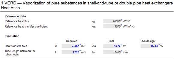
Reference data
The second value block contains data for the reference heat flux q0, the reference heat transfer coefficient a0 and properties of the medium to be evaporated at 10% of the critical pressure. The properties at 10% of the critical pressure are only necessary for vaporization in horizontal tubes.
The values of the reference heat flux q0 and the reference heat transfer coefficient a0 of many substances are listed in a table and can be called up from the program by pressing the F3 function key. Highlight the input field of the reference heat transfer coefficient a0 and press F3.
Reference heat transfer coefficients a0 not listed in this table can be calculated with the module HABA by using their critical data. Call HABA by 'Atlas' + 'Chapter' + 'Alphabetical list of modules' + 'HABA'.
If you use the PROP module for calculating the properties, the HABA module automatically calculates the reference heat transfer coefficient.
Heat transfer coefficients α0 and normalized values of the heat flux at tube-side evaporation
Heat transfer coefficients α0 at p0* = 0.1, Ra0 = 1 · 10-6 m and normalized values of heat flux q0. |
|||||
|
Medium |
Formula |
Pc |
M |
q0 W/m² |
α0 |
|
Methane |
CH4 |
46.0 |
16.04 |
20000 |
8060 |
|
Ethane |
C2H6 |
48.8 |
30.07 |
20000 |
5210 |
|
Propane |
C3H8 |
42.4 |
44.10 |
20000 |
4000 |
|
n-Butane |
C4H10 |
38.0 |
58.12 |
20000 |
3300 |
|
n-Pentane |
C5H12 |
33.7 |
72.15 |
20000 |
3070 |
|
Isopentane |
C5H12 |
33.3 |
72.15 |
20000 |
2940 |
|
n-Hexane |
C6H14 |
29.7 |
86.18 |
20000 |
2840 |
|
n-Heptane |
C7H16 |
27.3 |
100.20 |
20000 |
2420 |
|
Cyclohexane |
C6H12 |
40.8 |
84.16 |
20000 |
2420 |
|
Benzene |
C6H6 |
48.9 |
78.11 |
20000 |
2730 |
|
Toluene |
C7H8 |
41.1 |
92.14 |
20000 |
2910 |
|
Diphenyl |
C12H10 |
38.5 |
154.21 |
20000 |
2030 |
|
Methanol |
CH4O |
81.0 |
32.04 |
20000 |
4980 |
|
Ethanol |
C2H6O |
63.8 |
46.07 |
20000 |
3690 |
|
n-Propanol |
C3H8O |
51.7 |
60.10 |
20000 |
3170 |
|
Isopropanol |
C3H8O |
47.6 |
60.10 |
20000 |
2920 |
|
n-Butanol |
C4H10O |
49.6 |
74.12 |
20000 |
2750 |
|
Isobutanol |
C4H10O |
43.0 |
74.12 |
20000 |
2940 |
|
Acetone |
C3H6O |
47.0 |
58.08 |
20000 |
3270 |
Heat transfer coefficients α0 at p0* = 0.1, Ra0 = 1 · 10-6 m and normalized values of heat flux q0. |
||||||
|
Medium |
Formula |
Pc |
M |
q0 W/m² |
α0 |
|
|
Fluorotrichloromethane |
CFCI3 |
R11 |
44.0 |
137.37 |
20000 |
2690 |
|
Difluorodichloromethane |
CF2Cl2 |
R12 |
41.6 |
120.91 |
20000 |
3290 |
|
Trifluorochloromethane |
CF3CI |
R13 |
38.6 |
104.47 |
20000 |
3910 |
|
Trifluorobromemethane |
CF3Br |
R13B1 |
39.8 |
148.93 |
20000 |
3380 |
|
Difluorochloromethane |
CHF2CI |
R22 |
49.9 |
86.47 |
20000 |
3930 |
|
Trifluoromethane |
CHF3 |
R23 |
48.7 |
70.02 |
20000 |
4870 |
|
Trifluorotrichloroethane |
C2F3CI3 |
R113 |
34.1 |
187.38 |
20000 |
2180 |
|
Tetrafluorodichloroethane |
C2F4Cl2 |
R114 |
32.6 |
170.92 |
20000 |
2460 |
|
Pentafluorochlorethane |
C2F5CI |
R115 |
31.3 |
154.47 |
20000 |
2890 |
|
1.1- Dichloro-2.2.2-trifluoroethane |
C2HCl2F3 |
R123 |
36.7 |
152.93 |
20000 |
2600 |
|
1.1.1.2- Tetrafluoroethane |
C2H2F4 |
R134a |
40.6 |
102.03 |
20000 |
3500 |
|
I.1-Difluoroethan |
C2H4F2 |
R152a |
45.2 |
66.05 |
20000 |
4000 |
|
Hexafluorochloropropane |
C3HF6CI |
R226 |
30.6 |
186.48 |
20000 |
3700 |
|
Heptafluoropropane |
C3HF7 |
R227ea |
29.3 |
170.03 |
20000 |
3800 |
|
Cyclooctafluorobutane |
C4F8 |
RC318 |
28.0 |
200.03 |
20000 |
2710 |
|
Chlorodifluoromethane/ Chloropentafluoroethane-Aceotropic |
CHF2Cl |
R502 |
40.8 |
111.6 |
20000 |
2900 |
Heat transfer coefficients α0 at p0* = 0.1, Ra0 = 1 · 10-6 m and normalized values of heat flux q0. |
|||||
|
Medium |
Formula |
Pc |
M |
q0 W/m² |
α0 |
|
Chloromethane |
CH3CI |
66.8 |
50.49 |
20000 |
4790 |
|
Tetrachloromethane |
CCI4 |
45.6 |
153.82 |
20000 |
2320 |
|
Tetrafluoromethane |
CF4 |
37.4 |
88.0 |
20000 |
4500 |
|
Helium I |
He |
2.275 |
4.0 |
1000 |
2000 |
|
Hydrogen (Para) |
H2 |
12.97 |
2.02 |
10000 |
1220 |
|
Neon |
Ne |
26.5 |
20.18 |
10000 |
8920 |
|
Nitrogen |
N2 |
34.0 |
28.02 |
10000 |
4380 |
|
Argon |
Ar |
49.0 |
39.95 |
10000 |
3870 |
|
Oxygen |
O2 |
50.8 |
32.0 |
10000 |
4120 |
|
Water |
H20 |
220.64 |
18.02 |
150000 |
25580 |
|
Ammonia |
NH3 |
113.0 |
17.03 |
150000 |
36640 |
|
Carbon dioxide |
CO2 |
73.8 |
44.01 |
150000 |
18890 |
|
Sulfur hexafluoride |
SF6 |
37.6 |
146.05 |
150000 |
12230 |
© Springer Verlag Berlin Heidelberg 2013
Heat transfer coefficients α0 at p0* = 0.1, Ra0 = 1 · 10-6 m and reference values of the heat flux q0
|
|
|||
|
Fluid |
Formula |
Crit. pressure |
α0 |
|
Pc |
α0,exp |
||
|
bar |
W/(m²K) |
||
|
Methane |
CH4 |
45.99 |
7200 |
|
Ethene |
H2C=CH2 |
50.42 |
4200 |
|
Ethane |
CH3CH3 |
48.72 |
4600 |
|
Propene |
H2C=CHCH3 |
45.55 |
4200 |
|
Propane |
CH3CH2CH3 |
42.51 |
4300 |
|
n-Butane |
C4H10 |
37.96 |
3600 |
|
i-Butane |
C4H10 |
36.29 |
3700 |
|
n-Pentane |
C5H12 |
33.70 |
3300 |
|
i-Pentane |
C5H12 |
33.78 |
3200 |
|
n-Hexane |
C6H14 |
30.34 |
3200 |
|
Cyclohexane |
C6H12 |
40.75 |
3000 |
|
n-Heptane |
C7H16 |
27.36 |
2900 |
|
Benzene |
C6H6 |
48.94 |
2900 |
|
Toluene |
C7H8 |
41.26 |
2800 |
|
Diphenyl |
C12H10 |
38.47 |
2100 |
|
Methanol |
CH3OH |
82.16 |
5150 |
|
Ethanol |
CH3CH2OH |
61.31 |
4350 |
|
n-Propanol |
CH3CH2CH2OH |
50.50 |
3750 |
|
2-Propanol |
CH3CHOHCH3 |
47.60 |
3950 |
|
n-Butanol |
CH3CH2CH2CH2OH |
44.10 |
2600 |
|
i-Butanol |
CH3CH3CHCH2OH |
42.95 |
4500 |
|
2-Butanol |
CH3CHOHCH2CH3 |
41.94 |
3400 |
|
Ethanal |
CH3CHO |
55.50 |
3500 |
|
Acetone |
CH3COCH3 |
47.0 |
3300 |

|
|
||||
|
Fluid |
Formula |
ASHRAE |
Crit. pressure |
α0 |
|
Pc |
α0,exp |
|||
|
bar |
W/(m²K) |
|||
|
Trifluoromethane |
CHF3 |
R23 |
48.32 |
4800 |
|
Difluoromethane |
CH2F2 |
R32 |
57.82 |
5000 |
|
Pentafluoroethane |
CHF2CF3 |
R125 |
36.18 |
4400 |
|
1,1,1,2-Tetrafluoroethane |
CH2FCF3 |
R134a |
40.59 |
4200 |
|
1,1,1-Trifluoroethane |
CH3CF3 |
R143a |
37.61 |
4700 |
|
1,1-Difluoroethane |
CH3CHF2 |
R152a |
45.17 |
4600 |
|
2,3,3,3-Tetrafluorprop-1-en |
H2C=CFCF3 |
R1234yf |
32.18 |
3000 |
|
Heptafluoropropane |
CHF2CF2CF3 |
R227ea |
29.25 |
4100 |
|
R125/R143a, aceotropic |
(s. R125 & R143a) |
R507 |
37.05 |
4200 |
|
Cyclooctafluorobutane |
C4F8 |
RC318 |
27.78 |
4200 |
|
Tetrafluoromethane |
CF4 |
R14 |
37.50 |
4750 |
|
1,1-Dichloro-2,2,2-trifluoroethane |
CHCl2CF3 |
R123 |
36.62 |
3000 |
|
Fluorotrichloromethane |
CFCl3 |
R11 |
44.08 |
2800 |
|
Difluorodichloromethane |
CF2Cl2 |
R12 |
41.36 |
4000 |
|
Trifluorochloromethane |
CF3Cl |
R13 |
38.79 |
3900 |
|
Trifluorobromemethane |
CF3Br |
R13B1 |
39.70 |
3500 |
|
Difluorochloromethane |
CHF2CI |
R22 |
49.90 |
3900 |
|
Trifluorotrichloroethane |
CF2ClCFCl2 |
R113 |
33.92 |
2650 |
|
Tetrafluorodichlorethane |
CF2ClCF2CI |
R114 |
32.57 |
3800 |
|
Pentafluorchlorethane |
CF2CICF3 |
R115 |
31.29 |
4200 |
|
R22/R115, aceotropic |
(s. R22 & R115) |
R502 |
40.17 |
3300 |
|
|
|||
|
Fluid |
Formula |
Crit. pressure |
α0 |
|
Pc |
α0,exp |
||
|
bar |
W/(m²K) |
||
|
Chloromethane |
CH3Cl |
66.79 |
4400 |
|
Tetrachloromethane |
CCl4 |
45.60 |
3200 |
|
Sulfur hexafluoride |
SF6 |
37.55 |
3700 |
|
Water |
H2O |
220.64 |
5600 |
|
Ammonia |
NH3 |
113.33 |
7000 |
|
Oxygen |
O2 |
50.43 |
9500 |
|
Nitrogen |
N2 |
33.96 |
10000 |
|
Carbon dioxide |
CO2 |
73.77 |
5500 |
|
Argon |
Ar |
48.63 |
8200 |
|
Neon |
Ne |
26.79 |
20000 |
|
Hydrogen |
H2 |
12.96 |
24000 |
|
|
|||
|
Fluid |
Formula |
Crit. pressure |
α0 |
|
Pc |
α0,exp |
||
|
bar |
W/(m²K) |
||
|
Helium |
He |
2.27 |
2000 |

© Springer Verlag Berlin Heidelberg 2013
The end of the calculation is reached, when the required bundle length or required heat transfer area is determined. The final heat transfer area and final bundle length are determined by using the overdesign. The overdesign specifies the ratio of final heat transfer area and required heat transfer area in % (see Rating by overdesign).
The calculation can be influenced in the required direction by modification of the variables. The quality of the calculation can for instance be determined by a ‘parameter study’ giving information about how the exchanger reacts, when the process parameters are changed.
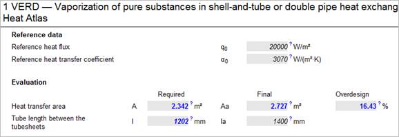
Evaluation
If no standard dimensions, i.e. no default variables for the tube-side and shell-side dimensions, have been specified, all geometrical data must be entered. For that the third value block in the VERD input / output mask is provided.
When all required data have been entered the tubesheet is generated automatically by VERD.
>> The calculation of evaporators with 2 shell-side passes (longitudinal baffle) is not possible with VERD.
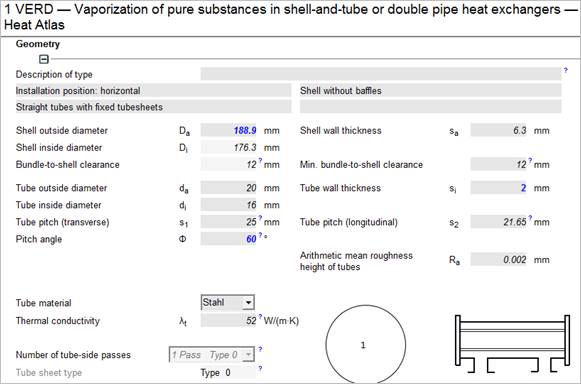 Geometrical data
Heat exchangers are usually designed on the basis of fixed standard dimensions. This applies for instance to the shell diameter, the tube pitch and tube dimensions, the type of the tube-side head and values specified by e.g. TEMA standard.
Additionally the tube-side and shell-side velocities play an important role. The shell-side velocity and the TEMA standard determine the distance between the segmental baffles. The input of these values in the ‘basic data‘ menu leads to an exchanger design lying within the industrial standards.
By default, VERD uses shells, which are saved in the database and can be selected in the ‘Selection of basic data’ form. If you want to use a shell differing from these default values, you need to deactivate the option ‘Default values’ in the ‘Basic Input’ menu. Then you can enter the inside diameter of the shell.
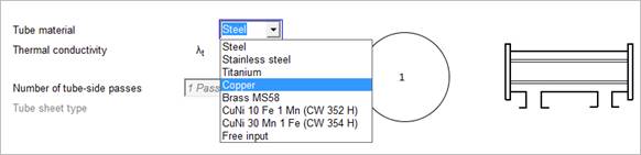
With shell-side evaporation (pool boiling) the material data of the evaporator tubes (thermal conductivity, density and specific heat capacity) are required for calculating the heat transfer coefficient.
With tube-side evaporation (nucleate boiling in pipe flow) only the thermal conductivity of the of the evaporator tubes is required.
It is possible to select or change the material data in the VERD input mask. Click on the field ‘Tube material’ and select a new material from the selection box.
If you select ‘Free input’ the material data on the VERD input masks are deleted and have to be entered manually (see Tube material).
VDI Heat Atlas chapters H2 (pool boiling of saturated liquids) and H3.4 (flow boiling of saturated liquids) are the base of the calculation of the heat transfer coefficient at the evaporation.
When vaporizing in horizontal tubes the evaporator is segmented into 5 increments of the same size. For each increment the flow pattern and the corresponding heat transfer coefficient is determined.
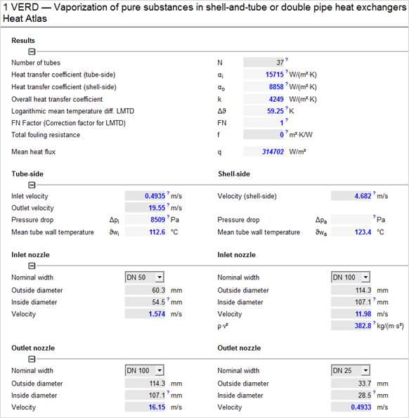
Pressure drops are calculated after you have entered the inlet and the outlet nozzle diameter.
With evaporation around the tubes, no shell-side pressure drop is calculated.
The VERD program can calculate a condenser with condensation of any pure substance.
For the calculation of the condensation process it is important that the vapour enters the condenser with saturated steam temperature, which means not superheated, and that the condensate leaves the condenser with the same temperature, which means not subcooled.
If ‘Steam condensation’, ‘NH3 condensation’ or ‘CO2 condensation’ has been selected in the ‘Basic data selection’ dialog box as condensing medium, a condensation of saturated steam (water steam), ammonia or is presumed and VERD selects the condensation set-up to calculate the heat transfer. Required input data are either ‘condensation pressure (Psatt) or condensation temperature (Tsatt). The properties of the steam and the condensate are calculated automatically.
For any pure substance to be condensed, ‘Free input‘ has to be selected for the condensing medium and ‘condensation’ for the physical state in the ‘Basic data selection’.
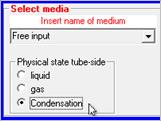
In the ‘Visual VERD’ input mask the condensation pressure as well as condensation temperature have to be entered. After you have entered the pressure and the temperature, the program switches to the SDAT module automatically. In the SDAT input mask enter the properties of the condensate / boiling liquid (density, specific heat capacity, viscosity and thermal conductivity) in the upper part of the data sheet). In the bottom part of the sheet the properties of the vapour (density, specific viscosity and thermal conductivity) and the heat of evaporation have to be entered. As soon as all required data have been entered, the program automatically switches to the VERD input mask.
For shell-side condensation, the shell-side pressure drop is not calculated.