Coil Type Flue Gas Heat Exchangers (economisers)
The WAK program designs coil type economizers with multiple helically-coiled tube bundles. Water heaters or thermal oil heaters can be calculated. The standard medium is hot oil on the tube side and flue gas on the shell side. User-specific data for the flue gas can be entered or you may select standard compositions for typical gas, fuel, or solid fuel combustions.
Calculation of horizontal or vertical exchanger arrangement is possible. The flow pattern is either countercurrent or cocurrent. The program suggests parallel flow in coils and annulus.
You can:
· Use 2 - 14 concentric tube baskets with or without a flow directing unit
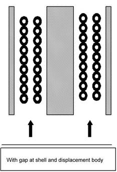
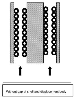
· Decide if the most inner or most outer basket touches the shell or displacement body or can be constructed with a gap
· Use gap widths at displacement body and at shell independent from each other
· Specify the tube geometry and number of tubes in the coils freely.
An improved calculation of the flue gas-side heat transfer allows longitudinal pitch ratios from 1.0 on (the tubes are narrowly coiled and welded). In the calculation, the effect of radiation from the flue gas is taken into account.
The maximum film temperature is calculated for the coil with the lowest heat transfer coefficient and for the section with the highest temperature level.
In the tubes
H2O Water
T-OIL Thermal oils
OEL Several transmission oil, hydraulic oils, machine oils, thermal oils for different ISO
HFO Heavy fuel oils (HFO 030 – HFO 700 and Diesel, gasoil and lube oil)
S-DAT Free input of physical properties
PROP* Physical properties generator PROPER from Lauterbach Verfahrenstechnik GmbH
FRIG* Refrigerants
CO2* Carbon dioxide
Around the tubes
RGAS Flue gases
LUFT Air
S-DAT Free input of physical properties
PROP* Physical properties generator from Lauterbach Verfahrenstechnik GmbH
FRIG* Refrigerants
CO2* Carbon dioxide
*) at extra charge
The calculation of the pressure drop and of the volume flows is based on L1.2 (VDI Heat Atlas). The volume flows in the single tubes are varied iteratively to achieve the same pressure drop in every coil.
With the iteratively determined volume flows in the tubes, the inner heat transfer coefficient for every coil is calculated based on chapter G3 (VDI Heat Atlas).
Additionally, the program calculates an area standardized heat transfer coefficient. It is considered if the flow around the most inner and the most outer coil is only partial or complete.
The gaps around the tubes are flown parallel. The calculation of the pressure drop and of the volume flows is based on L1.4 (VDI Heat Atlas).
For the gaps at the displacement body, the transverse pitch is determined to match the maximum velocity in the shell with the velocity in the narrowest cross section of a tube bundle with this pitch.
With the iteratively determined volume flows in the tubes, the heat transfer coefficients (convective) are calculated based on equations by F. Brandt [2]. The calculation is performed in the WROK module. Additionally, the program calculates an area standardized heat transfer coefficient. It is considered if the flow around the basket is on both sides.
The heat transferred by radiation of the
flue gas to the tube walls is calculated at two points according to
H. Haussen [3] and is then interpolated across the whole exchanger. The calculation of the heat flux at these two points is based o
chapter K3 (VDI Heat Atlas).
Using the heat transfer coefficients, the heat flux in the tube wall and with considering a possible fouling at the tube outer wall, the overall hat transfer coefficient k is calculated. With this overall heat transfer coefficient k, the heat duty and the logarithmic temperature difference a required heat transfer area Areq is determined. The ratio of Areq and Aact shows as performance factor if the exchanger is sufficiently dimensioned to transfer the required heat duty.
For calculating the maximum film temperature, the coil with the lowest inner heat transfer coefficient and the section with the highest temperature is used.
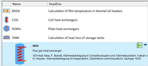
Start the program by double-clicking the icon ‘Flue Gas Heat Exchanger’ in the ‘Coil’ program group.
Or in the COIL Treeview.
When you have started the program, the following selection mask of WAK is displayed.
Select the number of coils, the flow arrangement, the position of the heat exchanger (from the point of view of the flue gas) and the tube-side medium.
Confirm with "OK".
Then you will receive the input mask of WAK, where you can find the relevant variables. Enter your design values:
We want to design a flue gas heat exchanger with the following data:
|
Amount of flue gas |
7000 m³/h (standard volume flow) |
|
Flue gas temperatures Tin/Tout |
600°C / 250°C |
|
In the tubes |
water |
|
Water temperatures Tin/Tout |
130°C / 160 °C |
|
Water pressure |
10 bar |
The flue gas is combustion gas from burned fuel oil. For process-technical reasons, the outlet temperature of the heat exchanger must not exceed 250°C.
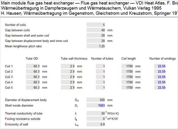
The tube dimensions for all coils are the same with 60.3mm x 2.9mm
1. Start the WAK program by double-clicking the icon
2. The following selection mask appears
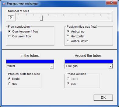
We assume that 5 coils are required. The flue gas flows the exchanger vertically from the bottom to the top. As tube side medium, we select water.
When confirming with OK, the input mask is displayed.
Enter the geometrical data and the known volume flows. In this example, no fouling is considered for the moment.
When you have entered the pressure and the temperature of the flue gas, the program asks for the type of combustion.
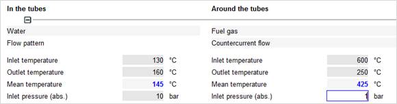
In our case ‘Flue gas from fuel oil’.
Enter the rest of the required data.
After you have entered all inlet and outlet temperatures, and the standard volume flow of the flue gas, the exchanger is calculated thermally and hydraulically.
All relevant results are displayed in the input masks of the according chapters.
The evaluation of the heat exchanger is done by the performance factor LZ. The performance factor is defined as ratio of actual heat transfer area Aact and the required heat transfer area Areq.

The performance factor LZ should always be > 1.
In this case the perormance factor LZ = 0,917, this means the exchanger does only have 91.7 % of the heat transfer area, which would be required to fulfil the demanded duty; there is an underdesign of 8.3 %.
The heat exchanger length increases slightly, when you increase the coil length.
Now, the performance factor is 1.181 i.e. the exchanger has an area reserve of 18.1 %.
Additionally, you can consider the fouling of the outer heat transfer area by entering a fouling resistance.
We have integrated tables with fouling resistances of several media in the program. Simply press F3 when the input field fouling is highlighted or click the blue question mark.
Enter 0.00018 m² · K / W as fouling resistance.
Now, the performance factor is 1.175.
You can get a nice overview of the thermal and hydraulic properties of the exchanger by clicking the button ‚Calculating values‘:
In this case, you get the following values:
[1] VDI Heat Atlas
[2] F.Brandt, Wärmeübertragung in
Dampferzeugern und Wärmetauschern,
Band 2, Vulkan-Verlag, Essen 1995
[3] Helmuth Haussen,
Wärmeübertragung in Gegenstrom, Gleichstrom und Kreuzstrom
Springer-Verlag, 1976