Calculation of the double shell connection
When the RING module is started, a selection form appears in which various designs are specified. The selection of a type is confirmed with "OK".
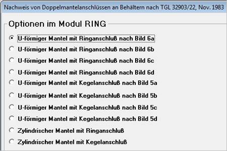
For more information on the various designs, refer to the chapter Design types .
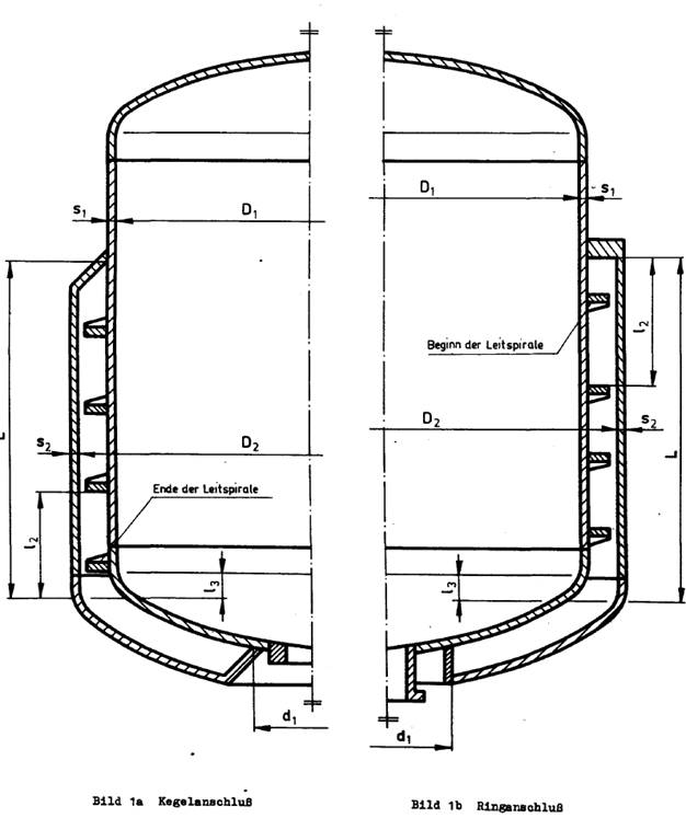
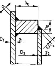
U-shaped double shell constructions are usually designed with cone connection (left in the picture) or with ring connection (right in the picture).
According to the guideline, the following designs are distinguished, which you can select on the selection screen when starting the program.
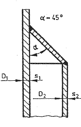
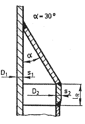
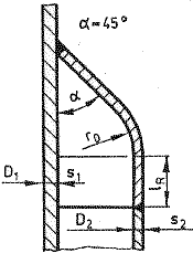
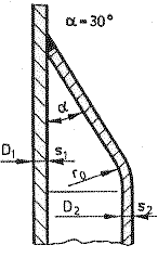
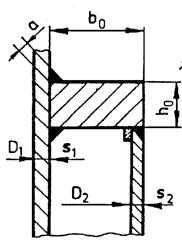
Information on the dimensions of the various designs is provided in the following graphics.
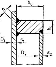
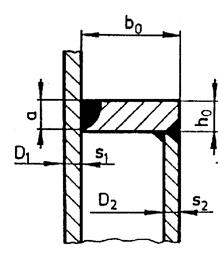
The different designs of the taper connections are summarized in the selection mask under the item "Cylindrical double wall with taper connection". The design type of the taper connection is to be selected in the input mask.
The different designs of the ring connections are summarized in the selection mask under the item "Cylindrical double wall with ring connection". The design type of the ring connection must be selected in the input mask.
For the cylindrical double shell constructions with ring connection, the direct input option of the weld seam values to be determined according to TGL 32903/02 has been omitted for reasons of clarity; please directly enter the required values for the calculated weld seam values according to Section 3.4.1.1) of the guideline.
The dead loads G1 and G2 apply an axial force to the taper or ring connection:
F = + G2 Support elements on the vessel
F = - G1 Support elements on the double shell
Load capacity verification for the axial force and the upper pressure in the double shell:
 (36)
(36)
[p2] according to formula (16) for taper connections and
according to formula (32) -for connection rings
A according to formula (8)
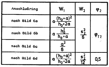
φ2 according to table 2 for ring connections, φ2 = φT2 for taper connections
Permissible overpressure in the double shell:
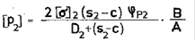 (16)
(16)
 (32)
(32)
Axial force factor:
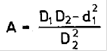 (8)
(8)
Table 2
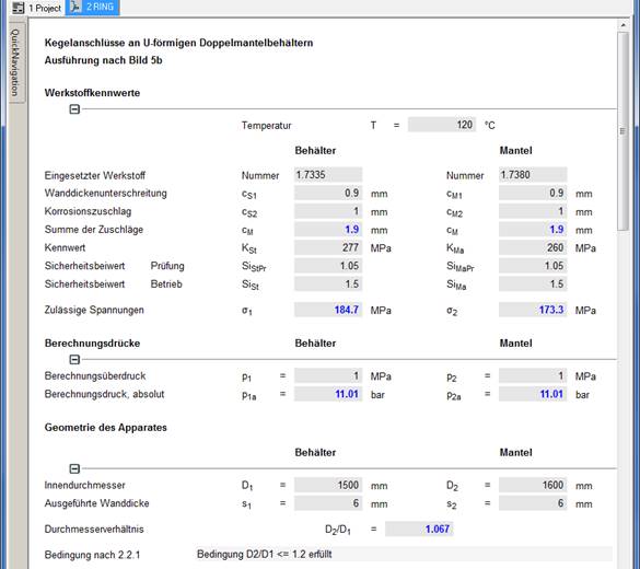
First select the desired design the selection screen by double-clicking or using the OK button. Then the input or calculation mask is shown. Here, materials and operating conditions as well as the geometric parameters are to be entered in any order.