Examples
If a heat exchanger has to generate a certain quantity of hot air, the outlet volume and temperature of the air should be specified. In this way the ‘hot’ side is determined and the exchanger area can be optimized by varying the inlet advance temperature or flow rate or by varying the physical dimensions of the exchanger.
In this case, the process stream determines the heat balance which is set by the process flow rate and the inlet and outlet temperatures. After that, the airside can be designed considering the total size, a maximum static fan pressure or other criteria.
The cooling of wet air may lead to the precipitation of water. The decisive factor for this process is the temperature of the fin surface. This means that water may be condensing although the relative humidity of the flowing air is smaller than the relative humidity in the saturated state.
There are no satisfactory relationships for the condensation on the air-side. The best results are achieved when the calculation is performed for pure gas flow and the air-side heat transfer is adapted to the heat balance.
From the point of view of the thermodynamics, this method is justified as long as the Lewis number is approximately 1 because of the analogy between heat transfer and mass transfer. This is valid up to a limited condensate quantity. If the condensate quantity is larger than this value, the spaces between the fins are filled with water and the heat transfer becomes worse. In such a case, the calculation is aborted and a message appears.
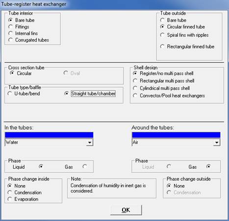
6000 kg/h process water is to be cooled from 110° C to 80° C. An air cooler with circular finned tubes is used.
The air enters the exchanger at 20° C and leaves it at 35°C.
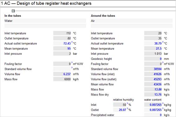
Temperatures and flows
Physical properties of media and pressure drop
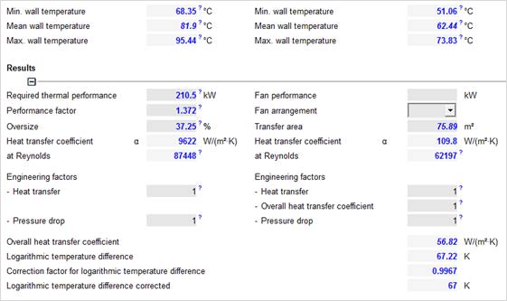
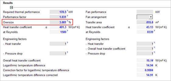
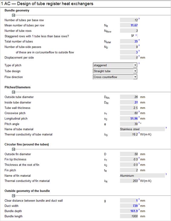
Exchanger is about 37% too large!
Result: Fewer tubes can be used!

Exchanger oversize now is only 14%
25000 m³/h of ambient air at 1.013 bar is to be cooled from 32° C to 12° C.
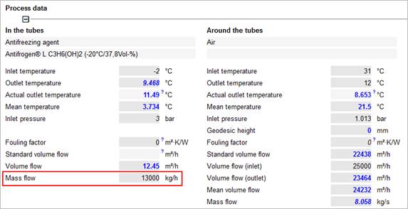
(13000 kg/h, 1-2 propylene glycol, freezing point -20° C, inlet temperature -2° C, pressure 3 bar).
A rectangular finned tube-type with fin-and-tube plates is used.
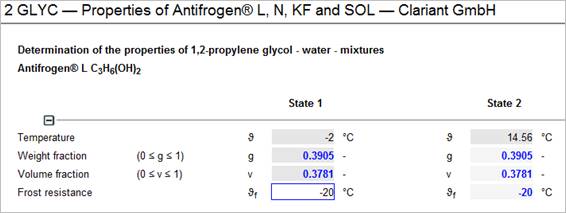
After selection of the medium in the tubes ‘Antifreeze Solvent’ (water-glycol mixtures)’ the user is asked to enter the frost resistance (input: -20° C).
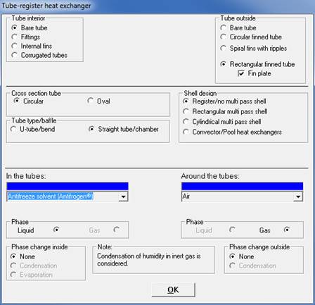
Confirm your selection with ‘OK’.
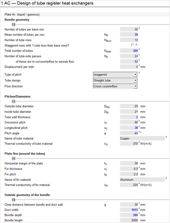
Tube material copper, fin material aluminum
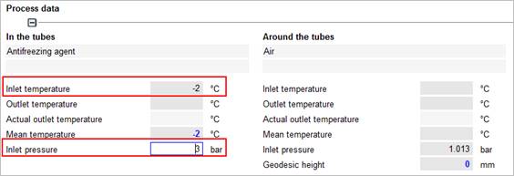
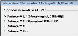
After input of the given data (inlet temperature and tube-side pressure), the user is asked to specify the glycol.
The selection (here: Antifrogen® L 1-2 propylene glycol) is confirmed by ‘OK’.
Enter the frost resistance of -20° C.
The mass flow of the glycol is entered according the capacity of the pump, e.g. 13000 kg/
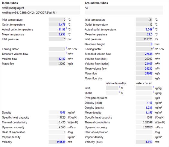
After having entered the temperatures of the air and the inlet volume flow, the program calculates the outlet temperature and recalculates the properties of the glycol.
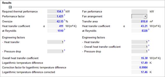
The performance factor is the ratio ‘Actual thermal performance / required thermal performance ‘.
In this example the heat exchanger can transfer more heat than required. (overdesign about 42%).
This means, the cooling task is securely performed.
Due to the overdesign (here: 42 %) different outlet temperatures will result during operation:
· in the tubes the outlet temperature will increase
· around the tubes the outlet temperature will go down.
A first estimation of the outlet temperatures can be done by the values in the fields ‚actual outlet temperatures’.
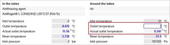
However, in this calculation there is no recalculation of the properties and
the hydraulic data. Therefore you have to
simulate the exchanger to get exact results.
Enter the actual outlet temperature into the field for the desired outlet temperature on the ‚Air‘ side: 9°C instead of 12°C. You may need to repeat this after the calculation procedure a couple of times until the differences between outlet temperature and 'outlet temperature within reach' are negligible. The data for performance, pressure loss etc. represent the actual operation of the air cooler!