Variable list
Get sample values by right mouse-click / values
Velocities in the nozzles should not exceed 30 m/s for gases and 1-2 m/s for liquids.
Velocities in the nozzles should not exceed 30 m/s for gases and 1-2 m/s for liquids.
Total number of tubes between the tube sheets. Is the same as number of bores in a tube sheet..
s. Tube arrangement and tube pitches
s. Tube arrangement and tube pitches
s. Tube arrangement and tube pitches
Get sample values by right mouse-click / values
Get sample values by right mouse-click / values
The fin material at the fin tip and at the root is usually of the same thickness.
s. Engineering factors
s. Relative humidity and water content
s. Tube arrangement and tube pitches
The Reynolds number implies if the flow is laminar or turbulent. Your main target should be turbulent flows (high velocities). The heat transfer is much more effective than in laminar flows.
For viscous media you can install turbulence-producing devices (corrugated tubes, twisted tapes, knubs etc.) to enhance the heat transfer.
s. Outer bundle geometry
Cover at inlet of the flow channel of the outside medium. It is only installed in very special cases to minimize bypass flows. Usually you can enter "0" !
s. Outer bundle geometry
s. Number of tube side passes ND
The requirement for a heat exchanger is to transfer a certain amount of heat (required by the process). Under the given conditions the exchanger is able to transfer only a specific amount of heat. The ratio of these values is the performance factor. This ratio should be a little more than 1.0. Undersized exchangers (performance factor <1) do not meet the requirements. Oversized exchangers (performance factor >1) are more expensive than necessary and may lead to disturbances in the process (e.g. too much cooling or heating).
The value "oversize" represents a certain reserve for fouling or process fluctuations. It should range from 2% - maximum 20%
s. Calculation of the Oversize in the AC program
s. Hydraulic calculation
s. Relative humidity and water content
s. Relative humidity and water content
s. Hydraulic calculation
The program chooses the tube-side nozzles to avoid too high velocities. If you enter the nozzle diameter manually, the program does not calculate them anymore
The program chooses the tube-side nozzles to avoid too high velocities. If you enter the nozzle diameter manually, the program does not calculate them anymore
s. Hydraulic calculation
s. Relative humidity and water content
s. Engineering factors
The lowest wall temperatures are required considering condensation (humidity, sulfuric acid) or formation of ice.
The highest wall temperatures are required for selecting the material and the strength calculation.
The wall temperatures are determined at the "coldest" and "hottest" location of the exchanger.
The mean wall temperatures influence the determination of the properties in the laminar sublayer.
s. Relative humidity and water content
s. Relative humidity and water content
s. Relative humidity and water content
s. Tube arrangement and tube pitches
Usually there are no shell-side nozzles (air coolers, tube register). If there are nozzles anyhow you need to enter the inside diameter of the nozzle. They are then considered for calculating the pressure drop.
Usually there are no shell-side nozzles (air coolers, tube register). If there are nozzles anyhow you need to enter the inside diameter of the nozzle. They are then considered for calculating the pressure drop.
Velocities in the nozzles should not exceed 30 m/s for gases and 1-2 m/s for liquids.
Velocities in the nozzles should not exceed 30 m/s for gases and 1-2 m/s for liquids.
The actual outlet temperatures are the actual operating temperatures of both media at the outlet.
In an oversized exchanger the hot medium is cooled down more than required. In an undersized exchanger, the hot medium is not cooled down sufficiently.
The calculation of the actual outlet temperatures is quite inaccurate for largely oversized or undersized exchangers
(s. Actual outlet temperature)
The actual outlet temperatures are the actual operating temperatures of both media at the outlet.
In an oversized exchanger the hot medium is cooled down more than required. In an undersized exchanger, the hot medium is not cooled down sufficiently.
The calculation of the actual outlet temperatures is quite inaccurate for largely oversized or undersized exchangers
(s. Actual outlet temperature)
|
|
vertical |
horizontal |
|
Induced |
|
|
|
Forced |
|
|
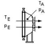
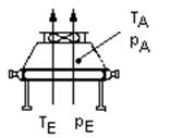
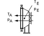
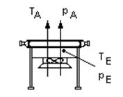
s. Engineering factors
s. Tube arrangement and tube pitches
This is just for documentation. The calculation is not affected.
This is just for documentation. The calculation is not affected.
s. Number of tubes per base row
s. Tube arrangement and tube pitches
s. Relative humidity and water content
s. Relative humidity and water content
s. Calculation of the Oversize in the AC program
s. Outer bundle geometry
s. Number of tube side passes ND
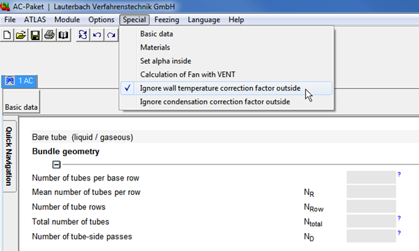
This correction factor considers changing of the physical properties at wall temperature and their influence on the heat transfer coefficient. By now, this effect is considered in the VDI Heat Atlas module chapter G7 and we highly recommend using the calculation of this module! As a consequence, the option ‘Ignore wall temperature correction factor outside‘ is activated by default since version 8.18.2 (August 2016). Only with older files, this option is deactivated for compatibility reasons. Nevertheless, you can set the option manually (s. screenshot).
s. Engineering factors
s. Engineering factors